Download
1 / 14
160 likes | 501 Vues
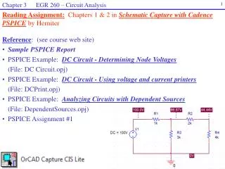
Chapter 3 EGR 260 – Circuit Analysis. 1. Reading Assignment: Chapters 1 & 2 in Schematic Capture with Cadence PSPICE by Herniter. Reference : (see course web site) Sample PSPICE Report PSPICE Example: DC Circuit - Determining Node Voltages (File: DC Circuit.opj)

E N D
Chapter 3 EGR 260 – Circuit Analysis 1 Reading Assignment:Chapters 1 & 2 in Schematic Capture with Cadence PSPICE by Herniter • Reference: (see course web site) • Sample PSPICE Report • PSPICE Example: DC Circuit - Determining Node Voltages • (File: DC Circuit.opj) • PSPICE Example: DC Circuit - Using voltage and current printers • (File: DCPrint.opj) • PSPICE Example: Analyzing Circuits with Dependent Sources • (File: DependentSources.opj) • PSPICE Assignment #1
Chapter 3 EGR 260 – Circuit Analysis 2 • ORCAD Capture (PSPICE) • The software is referred to by the generic name PSPICE. It was originally owned by MicroSim and then by ORCAD. It is currently owned by Cadence, but has kept the ORCAD name. Either of the following two versions can be used in this course (both are available for download on the course web site): • ORCAD 10.5 (best choice if using Windows XP) • Cadence Capture 16.5 (best choice if using Windows 7) • See the examples on the course web site. The examples contain numerous comments. A classroom demonstration will provide further examples. • It is recommended that you create a new folder for each PSPICE problem. The software will generate a large number of files within this folder. • Run the software by selecting Start -Programs – Cadence – ORCAD Capture
Chapter 3 EGR 260 – Circuit Analysis 3 Comparison - Evaluation Version versus Full Version • Evaluation Version • Limit of 64 nodes • Limit of 1 page schematic • Standard libraries for sources and basic components are available • EVAL library (eval.slb) contains a couple hundred models of components, such as transistors, diodes, 7400 series IC’s, etc. • Cost: Free • Some advanced features not included (such as printed circuit board layout) • Full Version • Unlimited number of nodes • Unlimited number of pages • Standard libraries for sources and basic components are available • Libraries for most commercially-available components available (tens of thousands of models). • Cost: Thousands of dollars (depends on the platform and the types of features needed)
Chapter 3 EGR 260 – Circuit Analysis 4 • Basic steps in creating and analyzing a circuit using PSPICE • (See examples on class web site for details and illustrations): • 1) Create a project • A) Select File – New – Project from the main menu • B) When the New Project box appears, specify the following: • Assign the project a Name (any name is fine) • Create project using Analog or Mixed Analog/Digital • Pick the Location (select Browse and then select Create Dir to make a new folder for your project) • C) If asked to create based on an existing project or create a blank project, select create a blank project.
Chapter 3 EGR 260 – Circuit Analysis 5 Basic steps in creating and analyzing a circuit using PSPICE • Draw the schematic • Select Place Part – a list of libraries and parts should appear (as shown to the right) • If no libraries appear, select Add Libraries and select all libraries listed in the PSPICE folder as shown below. • Select the desired part (such as R in the Analog library or Vsource in the Source library). • Use Ctrl+R to rotate the part as you place it on the schematic. Once it has been placed, it can be rotated, flipped, or mirrored by right-clicking on the part. • Continue clicking on the schematic to place multiple parts (such as several resistor) and then right click and select End Mode to stop.
Chapter 3 EGR 260 – Circuit Analysis 6 Basic steps in creating and analyzing a circuit using PSPICE • Draw the schematic • Select Place Wire and add wires to connect the parts. • Analysis of circuits in PSPICE is based on nodal analysis, so each circuit must contain a ground symbol. The ground symbol named 0 must be used. If this is omitted, a “floating nodes” error will occur during analysis. The ground is added using Place Ground. If the 0 ground is not available, select Add Library and you should find it in the PSPICE – SOURCE library. • Use the Net Alias tool to label each node (N1 button in version 10.5 or abc button in version 16.5 as shown to the right). • Double-click on the values next to each component to change their value.
Chapter 3 EGR 260 – Circuit Analysis 7 Basic steps in creating and analyzing a circuit using PSPICE • Create a simulation profile (select PSPICE – New Simulation Profilefrom the main menu) • A) If the PSPICE menu doesn’t appear, you may not have selected Schematic instead of Analog or Mixed Analog/Digital as required, so start over. • Any name is OK for the Simulation Profile • Select the type of analysis to be performed (see examples for more details). There are 4 types of analysis in PSPICE: • Bias Point (find node voltages and place voltages, currents, and power on the schematic) • DC Sweep (vary a source or component) • AC Sweep (vary frequency) • Transient (vary time)
Chapter 3 EGR 260 – Circuit Analysis 8 Basic steps in creating and analyzing a circuit using PSPICE • Analyze the circuit (select PSPICE – Runfrom the main menu) • View the results. Different types of results are available, including: • Output File - Select PSPICE – View Output Filefrom the main menu • Graphical results • Bias Points on the schematic (with a Bias Point Analysis) – see below
Chapter 3 EGR 260 – Circuit Analysis 9 • Component Values in PSPICE • PSPICE is not case-sensitive • Allowable prefixes are shown in the table below * Note that m or M are used for milli. Use MEG for mega, not M.
Chapter 3 EGR 260 – Circuit Analysis 10 Invalid resistor value (no space allowed) Valid resistor values • Component Values in PSPICE • When PSPICE reads a component value: • No space is allowed between the value and the prefix or unit name • PSPICE essentially only looks at the first letter after the value to see if it is a valid prefix. All other letters are ignored, so unit names can be entered in a variety of ways. Several examples of specifying a 100 k resistor are shown below:
Chapter 3 EGR 260 – Circuit Analysis 11 • Dependent sources in PSPICE • Located in the analog library (analog.olb) • Use E, F, G, and H (not EPOLY, FPOLY, GPOLY, and HPOLY) • Each source has a round symbol that can be thought of as the source. The other terminals are for the control variable. • Double click on the source to set the GAIN property (default value = 1). Be sure to change the property settings so that the GAIN is displayed. Textbook symbols: PSPICE symbols:
Chapter 3 EGR 260 – Circuit Analysis 12 • PSPICE Demonstration • If time allows and computers are available to the class, the instructor will lead • the class in creating and analyzing circuits using PSPICE. • Demonstration topics: • Launching the software and creating a project • Creating and analyzing schematics • Labeling nodes • Using dependent sources • Using voltage and current printers • Changing and displaying properties. In general, display any property that you set or change. • Adding text to a schematic: Select Place – Text from the main menu • Viewing results • Using Bias Points with a Bias Point analysis • Using the .OUT file with a DC sweep
Chapter 3 EGR 260 – Circuit Analysis 13 • PSPICE Demonstration (continued) • Two types of analysis will be demonstrated. Both types are required in • PSPICE Assignment #1. • Bias Point Analysis • Automatically finds all node voltages and places the results in the .OUT file. • Current, voltage, and power values for each component can also be printed on the schematic by selecting the following from the menu: • PSPICE - Bias Points - Enable • DC Sweep Analysis • Add voltage and current printers. Be sure to set their DC property to YES or they will not work. • No spaces allowed between value and unit for starting & ending value in sweep (similar to specifying values of components) • If the starting and ending values are the same, use an Increment of 1 • If the starting and ending values are different, a table of outputs will appear in the .OUT file for each printer used.
Chapter 3 EGR 260 – Circuit Analysis 14 • PSPICE Demonstration (continued) • Voltage printers & current printers • use their (DC =) property and display it • use a DC sweep (analysis type) or the printer is ignored! • Insert current printers like an ammeter (break the circuit and place in series) • Insert voltage printers like a voltmeter (across the component (in parallel)) • Look for the negative sign on the printer for correct polarity • Forms for voltage: V(R2), V(A), V(A,B), Yes • The results are printed in the .OUT file Add a current printer in series with R4 and a voltage printer in parallel with R5. Also set their DC properties. Suppose that the current through R4 and the voltage across R5 are needed.