Download
1 / 72
720 likes | 870 Vues
Test pumps serve as pressure generators for the testing, adjustment and calibration of mechanical and electronic pressure measuring instruments through comparative measurements. These units can be used in the laboratory or workshop, or on site at the measuring point. Easy operation By connecting the test item and a sufficiently accurate reference pressure measuring instrument to the test pump, the same pressure will act on both measuring instruments. By comparison of the two measured values at any given pressure value, a check of the accuracy and/or adjustment of the pressure measuring instrument under test can be carried out. Easy handling The model CPP1200-X comparison test pump is a hydraulic comparison test pump for generating pressure up to 1,200 bar. It is technically identical to the instrument base of the model CPB3800 pressure balance. The integrated dual-area spindle pump with switching valves enables rapid filling of the test system and smooth pressure generation.<br>For More Information visit on:- www.seeautomation.com<br>Our Mail I.D:- sales@seeautomation.com<br>Contact Us:- 91-11-22012324 , 8144883403<br>

E N D
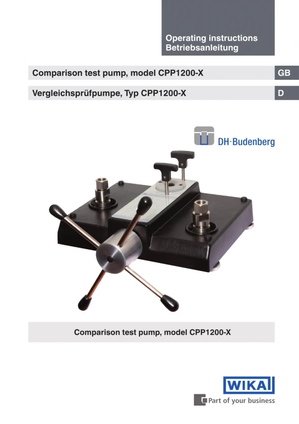
Operating instructions Betriebsanleitung Comparison test pump, model CPP1200-X GB Vergleichsprüfpumpe, Typ CPP1200-X D Comparison test pump, model CPP1200-X
GB Operating instructions model CPP1200-X Page 3 - 36 D Betriebsanleitung Typ CPP1200-X Seite 37 - 70 © 2013 WIKA Alexander Wiegand SE & Co. KG All rights reserved. / Alle Rechte vorbehalten. WIKA® is a registered trademark in various countries. WIKA® ist eine geschützte Marke in verschiedenen Ländern. Prior to starting any work, read the operating instructions! Keep for later use! Vor Beginn aller Arbeiten Betriebsanleitung lesen! Zum späteren Gebrauch aufbewahren! 14076968.01 12/2013 GB/D WIKA operating instructions model CPP1200-X 2
Contents Contents GB 1. 2. 2.1 2.2 2.3 2.4 2.5 3. 4. 4.1 4.2 4.3 4.4 5. 6. 6.1 6.2 6.3 6.4 6.5 6.6 6.7 7. 7.1 7.2 7.3 8. 9. 10. Appendix: EC Declaration of conformity for model CPP1200-X General information Safety Intended use Personnel qualification Personal protective equipment (P.P.E.) Special hazards Labelling, safety marks Specifications Design and function Description Scope of delivery Base unit Function Transport, packaging and storage Commissioning, operation Unpacking the comparison test pump Environmental requirement Assembly of base units Assembly Procedure Completion Cleaning gauges Maintenance, cleaning and recalibration Periodic maintenance Corrective maintenance Cleaning Faults Return and disposal Accessories 4 5 6 7 7 8 10 11 17 17 17 17 20 21 22 22 22 22 23 24 25 26 27 27 27 31 32 34 35 36 14076968.01 12/2013 GB/D Declarations of conformity can be found online at www.wika.com. WIKA operating instructions model CPP1200-X 3
1. General information 1. General information ■ The model CPP1200-X comparison test pump described in the operating instructions has been designed and manufactured using state-of-the-art technology. All components are subject to stringent quality and environmental criteria during production. Our management systems are certified to ISO 9001 and ISO 14001. GB ■ These operating instructions contain important information on handling the instrument. Working safely requires that all safety instructions and work instructions are observed. ■ Observe the relevant local accident prevention regulations and general safety regulations for the instrument's range of use. ■ The operating instructions are part of the product and must be kept in the immediate vicinity of the instrument and readily accessible to skilled personnel at any time. ■ Skilled personnel must have carefully read and understood the operating instructions prior to beginning any work. ■ The manufacturer's liability is void in the case of any damage caused by using the product contrary to its intended use, non-compliance with these operating instructions, assignment of insufficiently qualified skilled personnel or unauthorised modifications to the instrument. ■ The general terms and conditions contained in the sales documentation shall apply. ■ DH-Budenberg Ltd/WIKA reserve the right to change the contents or form of these operating instructions at any time without prior notice having been given. ■ Subject to technical modifications. ■ Further information: DH-Budenberg Ltd. - Internet address: - Relevant data sheet: - Application consultant: 14076968.01 12/2013 GB/D www.wika.de / www.wika.com CT 91.08 Tel.: (+44) 844 4060086 Fax: (+44) 844 4060087 E-mail: sales@dh-budenberg.co.uk WIKA operating instructions model CPP1200-X 4
1. General information / 2. Safety WIKA Alexander Wiegand SE & Co. KG - Internet address: - Relevant data sheet: - Application consultant: www.wika.de / www.wika.com CT 91.08 Tel.: (+49) 9372/132-0 Fax: (+49) 9372/132-406 E-mail: info@wika.com GB Explanation of symbols WARNING! ... indicates a potentially dangerous situation that can result in serious injury or death, if not avoided. CAUTION! ... indicates a potentially dangerous situation that can result in light injuries or damage to equipment or the environment, if not avoided. Information ... points out useful tips, recommendations and information for efficient and trouble-free operation. 2. Safety WARNING! Before installation, commissioning and operation, ensure that the appropriate comparison test pump has been selected in terms of pressure range, design and specific measuring conditions. Non-observance can result in serious injury and/or damage to the equipment. 14076968.01 12/2013 GB/D Further important safety instructions can be found in the individual chapters of these operating instructions. WIKA operating instructions model CPP1200-X 5
2. Safety 2.1 Intended use Test pumps serve as pressure generators for the testing, adjustment and calibration of mechanical and electronic pressure measuring instruments through comparative measurements. These pressure tests can take place in the laboratory or workshop, or on site at the measuring point. GB The comparison test pump features two connections, for test item and reference measuring instrument, which can be used in any order. If one connects the test item and a sufficiently accurate reference measuring instrument to the test pump, on actuating the pump, the same pressure will act on both instruments. By comparison of the two measured values at any given pressure value, a check of the accuracy and/or adjustment of the pressure measuring instrument under test can be carried out. The integrated dual-area spindle pump enables rapid filling of the test system and smooth pressure generation up to 1,200 bar. At the same time, the precise, adjustable spindle pump also enables fine pressure adjustment. A control schematic for pressure generation on the instrument base facilitates quick and easy operation. The pump is further characterised by the spindle which runs solely within the pump body. This eliminates any harmful bending moment from an externally running spindle and, especially for field operation, there is the advantage that dimensions of this pump do not alter during operation through the rotation of the spindle. The term “reference measuring instrument” in these operating instructions refers to any pressure measuring instrument, such as: pressure gauge, electrical pressure measuring instrument and pressure transmitter with electrical output. The comparison test pump system is only as accurate as the reference measuring instrument used. The reference measuring instrument should be regularly calibrated in order to ensure that its accuracy is maintained. The instrument has been designed and built solely for the intended use described here, and may only be used accordingly. The technical specifications contained in these operating instructions must be observed. Improper handling or operation of the instrument outside of its technical specifications requires the instrument to be taken out of service immediately and inspected by an authorised DH-Budenberg/WIKA service engineer. 14076968.01 12/2013 GB/D Handle mechanical precision measuring instruments with the required care (protect from humidity, impacts, strong magnetic fields, static electricity and extreme temperatures, do not insert any objects into the instrument or its openings). WIKA operating instructions model CPP1200-X 6
2. Safety If the instrument is transported from a cold into a warm environment, the formation of condensation may result in instrument malfunction. Before putting it back into operation, wait for the instrument temperature and the room temperature to equalise. GB The manufacturer shall not be liable for claims of any type based on operation contrary to the intended use. 2.2 Personnel qualification WARNING! Risk of injury should qualification be insufficient! Improper handling can result in considerable injury and damage to equipment. carried out by skilled personnel who have the qualifications described below. ■ The activities described in these operating instructions may only be ■ Keep unqualified personnel away from hazardous areas. Skilled personnel Skilled personnel are understood to be personnel who, based on their technical training, knowledge of measurement and control technology and on their experience and knowledge of country-specific regulations, current standards and directives, are capable of carrying out the work described and independently recognising potential hazards. Special operating conditions require further appropriate knowledge, e.g. of aggressive media. DH-Budenberg/WIKA can provide dedicated training courses on the correct use of our products. Please contact your local office for further details. 2.3 Personal protective equipment (P.P.E.) The personal protective equipment is designed to protect the skilled personnel from hazards that could impair their safety or health during work. When carrying out the various tasks on and with the instrument, the skilled personnel must wear personal protective equipment. 14076968.01 12/2013 GB/D Follow the instructions, displayed in the work area, regarding personal protective equipment! WIKA operating instructions model CPP1200-X 7
2. Safety The required personal protective equipment must be provided by the operating company. GB Wear safety goggles! Protect eyes from flying particles and liquid splashes. 2.4 Special hazards WARNING! To ensure safe working on the instrument, the operating company must ensure whenever required. regarding work safety, first aid and environmental protection and knows the operating instructions and, in particular, the safety instructions contained therein. ■ that suitable first-aid equipment is available and aid is provided ■ that the operating personnel are regularly instructed in all topics WARNING! Residual media on the comparison test pump can result in a risk to persons, the environment and the equipment. Take sufficient precautionary measures. 2.4.1 Mineral oils health and safety information DH-Budenberg/WIKA provide hydraulic mineral oil in containers up to 500 ml, labelled “ISO VG 22”, for use up to 4,000 bar in test pumps. It is no more hazardous than other common lubricating oils. It is the nature of the way in which this equipment is used, that there could be frequent and/or prolonged skin contact; in a few individuals this could give rise to skin irritation (Keratosis or Dermatitis). The use of an effective barrier cream and/or protective gloves will greatly reduce this possibility. 14076968.01 12/2013 GB/D WIKA operating instructions model CPP1200-X 8
2. Safety Description Closed flash point greater than 120 °C GB Storage not above 30 °C Oral LD 50 15 g per kg body weight Threshold limit value 5 mg/m³ CO2/dry chemical foam or water fog Soak with absorbent clay or proprietary absorbent Fire extinguishing media Spillage Waste disposal Burn or dump in approved area Emergency treatment of acute effects Ingestion Do not induce vomiting. Administer 250 ml milk or olive oil. The main hazard following accidental ingestion is aspiration of liquid into lungs. Send to hospital immediately Remove to fresh air, if nausea persists seek medical attention. Wash with copious amounts of water for at least 10 minutes. If irritation results or persists, obtain medical advice. Where skin rashes or other abnormalities occur as a result of prolonged or repeated contact, medical advice should be obtained as soon as possible. Aspiration Inhalation Eye contact Skin contact 2.4.2 Other liquids For some very particular applications we supply specially constructed liquids. Copies of manufacturer’s data can be sent on request. If the comparison test pump is used with water as the pressure medium, for pressures greater than 700 bar, it is recommended that a mixture of 90 % water and 10 % glycerine (by volume) is used. 14076968.01 12/2013 GB/D WIKA operating instructions model CPP1200-X 9
2. Safety 2.5 Labelling, safety marks Product label GB For an explanation of symbols, see below. Serial No. Pressure range Date of manufacture Pressure medium Explanation of symbols Before mounting and commissioning the instrument, ensure you read the operating instructions! CE, Communauté Européenne Instruments bearing this mark comply with the relevant European directives. 14076968.01 12/2013 GB/D WIKA operating instructions model CPP1200-X 10
3. Specifications 3. Specifications Specifications Model CPP1200-X GB Pressure range Pressure transmission medium Hydraulic fluid from mineral oil/clean water, free of calcium- carbonate 1) 2) Reservoir 170 cm³ 0 ... 1,200 bar Pressure connections Test item connection 2 x G ½ female thread, loose union connection, incl. adapter set to G ⅛, G ¼ and G ⅜ female threads 290 mm Distance between test connec- tions Piston of spindle pump Piston diameter, low-pressure piston Piston diameter, high-pressure piston Displacement 31.2 mm 12.7 mm approx. 10 cm³ Material Wetted parts Austenitic stainless steel, high tensile brass, nitrile rubber Permissible ambient conditions Operating temperature 0 ... 40 °C Instrument base Dimensions 401 x 397 x 155 mm (W x D x H), for details, see technical drawings 13.5 kg Weight 1) For operation with water as a medium, and for pressures greater than 700 bar, a mixture of 90 % water and 10 % glycerine (by volume) should be used. 2) Other pressure transmission media available on request. 14076968.01 12/2013 GB/D Storage case (optional) Material Wood Dimensions 664 x 614 x 380 mm (W x D x H) Weight 8.5 kg WIKA operating instructions model CPP1200-X 11
3. Specifications CE conformity Pressure equipment directive 97/23/EC (Module A) GB Approvals and certificates, see website For further specifications see WIKA data sheet CT 91.08 and the order documentation. Transport dimensions The comparison test pump in the standard version and standard scope of supply will be delivered in a single package with dimensions 590 x 490 x 380 mm. The weight is 18 kg net / 22 kg gross. 14076968.01 12/2013 GB/D WIKA operating instructions model CPP1200-X 12
3. Specifications Dimensions in mm Front view GB Side view 14076968.01 12/2013 GB/D WIKA operating instructions model CPP1200-X 13
3. Specifications Top view 2 GB 5 6 3 1 7 1 4 (1) Test connections (2) High-pressure shut-off valve (3) Low-pressure shut-off valve (4) Dual-area pump with star handle (5) Rotatable feet (6) Reservoir with sealing plug (7) Pressure generation control schematic 14076968.01 12/2013 GB/D WIKA operating instructions model CPP1200-X 14
3. Specifications Test item connection GB Adapter, see scope of delivery Sealing ring USIT 10.7 x 18 x 1.5 Oil collecting tray 14076968.01 12/2013 GB/D WIKA operating instructions model CPP1200-X 15
3. Specifications Liquids used A hydraulic mineral oil with viscosity 20 ... 37 cSt at 40 °C and viscosity grade VG20 to VG37 to ISO 3448 (BS 4231) is used for the CPP1200-X comparison test pump. Most users will be able to obtain locally suitable oil (see below) as used in hydraulic machinery. However, for the convenience of users we can supply a 500 ml bottle of oil, viscosity grade VG22. GB Oils suitable for test pumps The following oils are the commercially available oils suitable for use in test pumps. ISO 3448 viscosity grade VG22 Approx. SAE viscosity classification Shell Esso Mobil Tellus 22 Tellus R22 Tellus V32 DTE 24 Tellus 37 Tellus R37 Tellus T37 Tellus V37 Nuto H22 DTE 22 VG32 10W Nuto H32 DTE Oil Light VG37 Other liquids The model CPP1200-X comparison test pump is designed for use with mineral oils. If an end user wishes to use it on another fluid, it is the end user responsibility to ensure that the fluid is compatible with high tensile brass, stainless steel, mild steel, and nitrile rubber, which are the materials that will come into contact with the fluid. Fluids, which attack ABS, should be used with caution. Continual immersion of the cover in such fluids will cause deterioration. Spillages should be wiped off immediately. 14076968.01 12/2013 GB/D Wear safety goggles! Protect eyes from flying particles and liquid splashes. WIKA operating instructions model CPP1200-X 16
4. Design and function 4. Design and function 4.1 Description The model CPP1200-X comparison test pump features optimal characteristics for use in the laboratory, as well as the ruggedness needed for industrial applications. It is suitable for pressure generation up to 1,200 bar. Test item and reference measuring instrument are connected to the two test connections. GB 4.2 Scope of delivery 1 hexagon wrench key 3 mm A/F 2 x 30 mm A/F open-ended spanners 1 spirit level 4 level plates 1 bag of seals 1 pointer punch 1 pointer remover 1 test item connection ■ Base ■ Dual-area spindle pump for filling, pressure generation and fine pressure adjustment ■ 2 test connections with G ½ female thread, loose union connection ■ Adapter set for test item connection, G ½ B male to G ¼ and G ⅜ female threads ■ VG22 mineral oil (0.5 litre) ■ Tool and maintenance set consisting of: ■ Operating instructions in German and English language Cross-check scope of delivery with delivery note. 4.3 Base unit The model CPP1200-X base unit consists of a solid aluminium base plate mounted on four adjustable levelling feet, a spindle pump, reservoir, control valves, pipework to two stainless steel pressure connection blocks. The pipework and above mentioned assemblies are covered by an easy to clean ABS cover. 14076968.01 12/2013 GB/D WIKA operating instructions model CPP1200-X 17
4. Design and function Sectioned view of spindle pump GB K H J E 14076968.01 12/2013 GB/D G D F C WIKA operating instructions model CPP1200-X 18
4. Design and function 4.3.1 Spindle pump The spindle pump is bolted to the reservoir/high pressure cylinder block fastened to the base unit. A sectioned view of the pump is shown. The rotating handwheel (C) which is operated by the spokes (D) is attached to a threaded spindle (E). The spindle is supported in a sintered bearing (F). As the spindle (E) is rotated, it drives a non-rotating ram (E and K) forward, the thrust being taken by a needle thrust bearing (G). The large diameter of the ram (H) in the barrel of the pump (J) primes the pressure system and provides the low pressure up to approximately 140 bar (2,000 lb/in²). The small diameter of the ram (K) in the reservoir/ high pressure cylinder block provides the higher test pressures up to 1,200 bar (16,000 lb/in²). GB 4.3.2 Reservoir A liquid reservoir is provided on the top of reservoir/high pressure cylinder block. The reservoir is provided with a translucent cover to enable the reservoir level to be monitored. A plug in the middle of the reservoir cover enables the reservoir to be filled or topped up (the plug is removed whilst the test pump is in use). The reservoir contains enough liquid (approximately 150 cm³) to enable normal operation of the test pump to be carried out. Low pressure ram displacement = 60 cm³ High pressure ram displacement = 10 cm³ 4.3.3 Control valves Two control valves are provided on the top of reservoir/high pressure cylinder block. The valve mechanisms are built into the reservoir/high pressure cylinder block and they control the flow of liquid through internal drillings in the reservoir/high pressure cylinder block. The rear valve is referred to as valve A and is used to control the output from the high-pressure ram of the spindle pump. The front valve is referred to as valve B and is used to control the flow of liquid to and from the reservoir. 4.3.4 Connection blocks Pressure supply pipes from the spindle pump are terminated at two pressure blocks mounted on the base unit. The pressure blocks are fitted with threaded bosses projecting up through the cover plate of the base unit. These threaded bosses enable the delivered test connections to be directly screwed on to them, and it is also possible, using threaded adapters, to connect the various sizes of measuring instrument connections. Oil cups are fitted to the unit cover around the threaded bosses of the connection blocks to catch any oil drips from the gauge stand during gauge fitting and removal. 14076968.01 12/2013 GB/D WIKA operating instructions model CPP1200-X 19
4. Design and function 4.4 Function Operation of the comparison test pump is controlled by the two valves A and B on the top of the reservoir/high pressure cylinder block. When initially priming the system valves A and B are opened to fill the system with oil from the reservoir. Valve B is then closed with valve A left open and the spindle pump operated to provide the lower test pressures. To provide the higher pressures valve A is closed to seal off the test circuit from the low pressure part of the spindle pump and valve B is opened to allow the liquid in the low pressure part of the spindle pump to return to the reservoir as the pump is operated. This ensures that the pump can be operated without having to put large forces on the spindle pump handwheel. To release the test pressure the spindle pump is wound out and valve A is opened. GB Valve A Reservoir Valve B Hand pump 14076968.01 12/2013 GB/D WIKA operating instructions model CPP1200-X 20
5. Transport, packaging and storage 5. Transport, packaging and storage 5.1 Transport Check the model CPP1200-X comparison test pump for any damage that may have been caused by transport. Obvious damage must be reported immediately. GB 5.2 Packaging Do not remove packaging until just before mounting. Keep the packaging as it will provide optimum protection during transport (e.g. change in installation site, sending for repair or recalibration). 5.3 Storage Permissible conditions at the place of storage: ■ Storage temperature: -10 ... +50 °C ■ Humidity: 35 ... 85 % relative humidity Avoid exposure to the following factors: ■ Direct sunlight or proximity to hot objects ■ Mechanical vibration, mechanical shock (putting it down hard) ■ Soot, vapour, dust and corrosive gases ■ Potentially explosive environments, flammable atmospheres ■ Corrosive liquids Store the model CPP1200-X comparison test pump in its original packaging in a location that fulfils the conditions listed above. If the original packaging is not available, pack and store the instrument as described below: 1. Wrap the instrument in an antistatic plastic film. 2. Place the instrument, along with shock-absorbent material, in the packaging. 3. If stored for a prolonged period of time (more than 30 days), place a bag, containing a desiccant, inside the packaging. 14076968.01 12/2013 GB/D WIKA operating instructions model CPP1200-X 21
6. Commissioning, operation 6. Commissioning, operation 6.1 Unpacking the comparison test pump As soon as possible after delivery open the packaging of the comparison test pump and check that you have all the items detailed in the packing list (see chapter 4.2 “Scope of delivery”). As you are unpacking the items, examine them for signs of damage or breakage during transit. If any items are missing get in touch immediately with DH-Budenberg/WIKA to inform us of the shortage. GB 6.2 Environmental requirement When siting the comparison test pump not in a temperature controlled laboratory, look for an area that satisfies the following criteria as much as possible: ■ A constant temperature area free from draughts and sources of heat or cold ■ An area free from noise and vibration, constantly used pathways ■ A clean dry area free from corrosive liquids or vapours A strong, stable, level table or workbench with the capability of supporting the system with sufficient space to operate is required. 6.3 Assembly of base units Fastening base to bench The base is to be mounted on a firm, level table or bench about 0.9 m high. The centre line of the front adjustable feet of the unit should be about 40 mm from the front edge of the bench to allow adequate clearance for the handwheel. 1. Mark the position of the adjustable feet of the unit on the top of the bench. 2. Position a level plate at the centre of each of the adjustable feet of the unit and screw the plate to the bench to ensure that the comparison test pump is rigid. 3. Fit the base unit on the bench with the adjustable feet on the level plates and the handwheel shaft projecting over the front of the bench. 4. Screw in the four handwheel spokes into the hub. 5. Using the spirit level provided, level the test pump by adjusting the four knurled feet. 14076968.01 12/2013 GB/D WIKA operating instructions model CPP1200-X 22
6. Commissioning, operation 6.4 Assembly 6.4.1 Connection of the test item and the reference measuring instrument The instrument to be tested and the reference measuring instrument are inserted into the two test connections and can be oriented. It doesn’t matter which port is used for which instrument. GB To calibrate instruments with a rear-mount connection, an angular connector is available as an accessory. WARNING! Check that the seals in the test connections are seated correctly and are not worn. Replace them if necessary. It is important that any instrument that is to be connected is clean inside. As standard, the test connections are G ½ female. For calibrating instruments with other connection threads, the appropriate thread adapter can be used (see chapter 10 “Accessories”). 6.4.2 Filling the base unit with liquid 1. Remove filler plug from reservoir by prising plug out. (This plug should be left out whilst in use). 2. Open valves A and B. 3. Wind spindle pump handle fully clockwise. 14076968.01 12/2013 GB/D 4. Fill reservoir with appropriate liquid. Use the oil supplied or an approved substitute for oil systems. Do not use other liquids. Castor based oils, Skydrol, solvents or similar liquids will attack the seals fitted in the test pump. 5. Wind spindle pump handle fully anti-clockwise. WIKA operating instructions model CPP1200-X 23
6. Commissioning, operation 6. Top up reservoir if necessary. GB Wear safety goggles! Protect eyes from flying particles and liquid splashes. 6.4.3 Post assembly test 1. Carry out a test calibration of a known instrument (see chapter 6.6 "Procedure") to ensure that the unit is working correctly. 2. Release the pressure and remove the test instrument. To remove the instrument from the system, use the appropriate size of spanners on the top section of the pressure connection and on the body of the instrument only. Ensure that the lower part of the pressure connection is not rotated as this may release it from the base. 3. The system is now ready for use. When testing equipment with a large volume, the capacity of the spindle pump (65 cm³) may be insufficient to reach the pressure required. In this case, the equipment should be filled as far as possible with the liquid before connecting it to the system, so that the displacement needed is reduced. Dirty or chemically contaminated test items should not be fitted as they contaminate the system unless they are first cleaned. Wear safety goggles! Protect eyes from flying particles and liquid splashes. 14076968.01 12/2013 GB/D 6.5 Procedure 1. Fit instrument to be tested to a test connection. 2. Connect the reference measuring instrument to the other test connection. WIKA operating instructions model CPP1200-X 24
6. Commissioning, operation 6.5.1 To apply pressure For pressures up to 140 bar (2,000 lb/in²) GB 1. Close valve B (valve A remaining open). 2. Wind spindle pump handle clockwise. This will generate pressure up to approxi- mately 140 bar or 2,000 lb/in², as handle is wound in. When handle becomes stiff to rotate this will indicate that the pressure limit for this range has been reached. For pressures above 140 bar (2,000 lb/in²) 1. Close Valve A and open valve B. 2. Continue to wind spindle pump handle clockwise. This will generate pressure up to approximately 1,200 bar or 16,000 lb/in². 6.5.2 During calibration Increase the pressure via the spindle pump in the clockwise direction, or use the fine adjustment to approach the individual calibration points. The display of the pressure measuring instrument being tested can be compared with the reference measuring instrument at the individual calibration points. If there are still small air particles within the system, the generated test pressure will initially drop and must be readjusted accordingly. With higher pressures, a longer waiting time than with lower pressures should be expected until the steady-state condition has been reached. 6.6 Completion 1. After the test is finished wind spindle pump handle anti-clockwise to lower pressure. 2. Gently open valve A or B to release residual pressure. 3. Ensure that both valves A and B are fully open. 4. Remove device under test. 14076968.01 12/2013 GB/D The system is now ready for another test and any residual pressure is relieved. WIKA operating instructions model CPP1200-X 25
6. Commissioning, operation 6.7 Cleaning gauges This cleaning/degreasing process is only suitable for use with pressure gauges with either phosphor bronze, beryllium copper, Monel or stainless steel Bourdon tubes in the form of a "C". GB It is not advisable to degrease pressure gauges with steel Bourdon tubes since a very small amount of corrosion on the bore of a Bourdon tube can cause inaccuracies of reading and early failure of the tube. Wear safety goggles! Protect eyes from flying particles and liquid splashes. This method of cleaning is not suitable for use with pressure gauges which are fitted with coiled Bourdon tubes, nor any gauges which are to be used on oxygen, as complete removal of oil is not assured. Please contact DH-Budenberg/WIKA. Equipment This consists of a syringe and a special needle with the point bent through 90°. Instructions 1. Fill syringe with solvent (suitable cold degreasing liquid). 2. With gauge connection pointing upwards put needle into connection and insert by feel the point into the hole leading to the tube. 3. Inject the solvent. Ideally the tube should be half full. 4. Shake gauge in various attitudes to agitate solvent. 5. Suck solvent back into syringe, holding gauge at an angle. 6. Check that solvent removed is clean. To be sure that all oil has been removed, repeat cleaning process until solvent removed from gauge is as clean as that put in. 14076968.01 12/2013 GB/D WIKA operating instructions model CPP1200-X 26
6. Commissioning, operation / 7. Maintenance and cleaning GB Removing the solvent Filling with solvent Cleaning of gauges 7. Maintenance and cleaning 7.1 Periodic maintenance Repairs must only be carried out by the manufacturer. Cleaning the units and checking the liquid levels is the only periodic maintenance required. With normal use, no further maintenance should be necessary. If required, the system can be returned to the manufacturer for re-conditioning. Fluids, which attack ABS, should be used with caution. Continual immersion of the cover in such fluids will cause deterioration. Spillage’s should be wiped off immediately. 14076968.01 12/2013 GB/D 7.2 Corrective maintenance 7.2.1 General This section contains details on stripping the unit and replacing the spare parts which are listed (see chapter 10 "Accessories"). The component identification numbers in brackets in each procedure refer to the following figure. WIKA operating instructions model CPP1200-X 27
7. Maintenance and cleaning 10 9 GB 8 11 7 12 13 6 14 5 15 4 14076968.01 12/2013 GB/D 3 16 2 1 WIKA operating instructions model CPP1200-X 28
7. Maintenance and cleaning 7.2.2 Removing the cover 1. Drain as much oil as possible from the test pump by turning the spindle pump fully clockwise and using a drain screwed into the test connection. 2. Remove the oil cups by levering upwards carefully. 3. Slacken the socket set screw using a 3 mm hexagon wrench key and remove both handwheels. 4. Remove the four cover retaining screws and lift off the cover. GB 7.2.3 Reservoir seals 1. Unscrew two screws and remove the reservoir cover 2. Remove the O-ring seal (6) from the recess and the Seloc seal (7) from the screws. 3. On replacement ensure all sealing faces are absolutely clean and do not overtighten screws. 7.2.4 Valve seals 1. Unscrew the gland nut. 2. Unscrew the valve spindle and remove the bonded seal. 3. Slide gland nut off spindle. 4. Using a suitable hooked tool remove the O-ring seal (9) from the bore of the gland nut. Renew O-ring and bonded seal (10). 5. On replacement ensure that O-ring is correctly located in the groove and all sealing faces are clean. Remove all burrs from spindle. 7.2.5 Spindle pump 1. Using a 4 mm hexagon wrench key unscrew the six socket head cap screws secur- ing the hub locating plate. (These are positioned inside the recess in the back of the aluminium hub). 2. By carefully pulling the hub the complete ram assembly can now be withdrawn from the barrel (During this operation a container is required beneath the barrel to catch any liquid). 3. Unscrew the ram from the hub assembly. 14076968.01 12/2013 GB/D WIKA operating instructions model CPP1200-X 29
7. Maintenance and cleaning 4. The high pressure seal (12) and low pressure seal (15) can now be replaced. Before fitting the new seals check the ram is not scored on the locating diameters. 5. At this point the hub assembly should be checked for excess play indicating wear in the bearing and for wear in the screwed spindle and nut. If any wear is found it will be necessary to dismantle the hub assembly. 6. Check the bore of the block assembly (11) is not badly scored or pitted. If a replace- ment is required this item is supplied complete with valves. The block is attached to the base by socket head cap screws. 7. Re-assembly is a straightforward reversal of the above procedures. GB On assembly care should be taken to align the ram to prevent bending, or damage to the seals. Excessive force should not be used. The socket head cap screws are not spaced equally around the locating flanges so check hole alignment before inserting screws. 7.2.6 Hub assembly 1. Unscrew the ram from the spindle. NOTE: left hand thread. 2. Unscrew the spokes from the hub. 3. Knock out the spring pin (1), found at the bottom of one of the tapped spoke holes in the hub, using a punch 6 mm dia. Pull off hub. 4. The hub locating plate and thrust bearing can now be removed from the spindle. 5. If the flanged bush (2) is to be renewed, it should be pressed out of the locating plate and a new one pressed in squarely. 6. The thrust bearing (3) is renewed as a complete assembly. 7. The nut, pin and spindle sub-assembly (4) can only be replaced as a matched pair. Unscrew the nut from the ram, gripping in a soft jaw vice and screw in the new nut. 8. Assemble the thrust bearing, locating plate and hub on to the spindle, lubricating with molybdenum disulphide grease. 9. Clamp these items together to eliminate end play and re-assemble spring pin. If using new spindle drill through 6.3 mm diameter to fit spring pin (1). 10.Lubricate the thread with molybdenum disulphide grease and screw into ram nut. 14076968.01 12/2013 GB/D WIKA operating instructions model CPP1200-X 30
7. Maintenance and cleaning 7.3 Cleaning Cleaning the unit and checking the liquid levels. GB Oil operation Keep the system clean and free from spilt oil. Wipe out the oil cups under the gauge stands as necessary. Do not use any cleansing solvents as they may damage the seals. Ensure that the reservoir contains sufficient liquid to carry out any calibrations required. If necessary top up the reservoir with the same liquid that is already being used. Do not mix various types or brands of liquid in the pressure balance. If the oil in the test pump becomes dirty, attach a drain to the test connection and use the spindle pump to flush through clean oil.(An angle connection is suitable). The spindle pump should be turned fully clockwise before starting. Wear safety goggles! Protect eyes from flying particles and liquid splashes. For information on returning the instrument see chapter 9.1 "Return". 14076968.01 12/2013 GB/D WIKA operating instructions model CPP1200-X 31
8. Faults 8. Faults Faults Causes Measures GB Equipment does not provide any output pressure. No liquid in the test pump. Check that the test pump is filled with liquid. Fill the equipment with fluid as necessary. See chapter 6.5.1 "Filling the equipment with liquid". Valve B is open. Close valve B and try again. Component being tested has a large volume. Pre-fill component with liquid before test. Examine seals on equipment to ensure they are fitted correctly and are undamaged. Replace as necessary. Missing or damaged liquid seals shown by signs of unexplained liquid leaks. Valve B handwheel disconnected from spindle. Examine valve B. Tighten up nut securing handwheel to spindle as necessary. Valve B assembly or valve seat damaged. Examine condition of valve B and valve seat. Replace valve assembly or return test pump to DH-Budenberg/WIKA for overhaul as necessary. If unable to locate a cause. Return test pump to DH-Budenberg/WIKA for investigation. Equipment provides pressure but pressure decays to zero Incorrect operating procedure being used. Ensure that correct operating procedure is being followed (see chapter 6.6). Examine seals on equipment to ensure they are fitted correctly and are undamaged. Replace as necessary. Missing or damaged liquid seals shown by signs of unexplained liquid leaks. Valve A or Valve B valve assembly or valve seat damaged. Examine condition of valves A and B and valve seat. Replace valve assembly or return test pump to DH-Budenberg/WIKA for overhaul as necessary. 14076968.01 12/2013 GB/D If unable to locate a cause. Return test pump to DH-Budenberg/WIKA for investigation. WIKA operating instructions model CPP1200-X 32
8. Faults Faults Causes Measures Incorrect operating procedure being used. Ensure that correct operating procedure is being followed (see chapter 6.6). Equipment provides pressure but pressure decays when valves A and B are operated. GB If unable to locate a cause. Return test pump to DH-Budenberg/WIKA for investigation. Insufficient liquid in pressure balance. Check liquid level in reservoir. Fill reservoir with correct liquid as necessary (see chapter 6.5.1). Equipment provides pressure but pressure decays to lower value then remains steady. Air in the system Pre-fill component under test with appropriate liquid. If necessary re-fill pressure balance with appropriate liquid. If unable to locate a cause. Return test pump to DH-Budenberg/WIKA for investigation. Internal damage Return test pump to DH-Budenberg/WIKA for investigation. Incorrect operating procedure being used. Ensure that correct operating procedure is being followed (see chapter 6.6). If unable to locate a cause. Return test pump to DH-Budenberg/WIKA for investigation. Internal damage Return test pump to DH-Budenberg/WIKA for investigation. The spindle pump of the test pump becomes very stiff to operate when the test pump is being used in the range below 140 bar (2,000 lb/ in²). Incorrect operating procedure being used. Ensure that correct operating procedure is being followed (see chapter 6.6). The spindle pump of the test pump becomes very stiff to operate when the test pump is being used in the range over 140 bar (2,000 lb/ in²). 14076968.01 12/2013 GB/D If unable to locate a cause. Return test pump to DH-Budenberg/WIKA for investigation. WIKA operating instructions model CPP1200-X 33
8. Faults / 9. Return and disposal CAUTION! If faults cannot be eliminated by means of the measures listed above, shut down the test pump immediately, and ensure that pressure is no longer present, and secure the instrument from being put back into operation inadvertently. In this case, contact the manufacturer. If a return is needed, please follow the instructions given in chapter 9.1 "Return". GB 9. Return and disposal WARNING! Residual media on the test pump can result in a risk to persons, the environment and equipment. Take sufficient precautionary measures. 9.1 Return WARNING! Strictly observe the following when shipping the instrument: All instruments delivered to DH-Budenberg/WIKA must be free from any kind of hazardous substances (acids, bases, solutions etc.). When returning the instrument, use the original packaging or a suitable transport package. To avoid damage: 1. Drain all fluid from reservoir. 2. Wrap the instrument in an antistatic plastic film. 3. Place the instrument, along with the shock-absorbent material, in the packaging. Place shock-absorbent material evenly on all sides of the transport packaging. 4. If possible, place a bag, containing a desiccant, inside the packaging. 5. Label the shipment as transport of a highly sensitive measuring instrument. 14076968.01 12/2013 GB/D Information on returns can be found under the heading "Service" on our local website. WIKA operating instructions model CPP1200-X 34
9. Return and disposal 9.2 Disposal Incorrect disposal can put the environment at risk. Dispose of instrument components and packaging materials in an environmentally compatible way and in accordance with the country-specific waste disposal regulations. GB This marking on the instruments indicates that they must not be disposed of in domestic waste. The disposal is carried out by return to the manufacturer or by the corresponding municipal authorities (see EU directive 2002/96/EC). 10. Accessories Designation/Variant Order no. Storage case for CPP1200-X instrument base "BSP" adapter set for G ½ B male test item connector to G ⅛, G ¼, G ⅜ and G ½ female "NPT" adapter set for G ½ B male test item connector to ⅛ NPT, ¼ NPT, ⅜ NPT and ½ NPT female "Metric" adapter set for G ½ B male test item connector to M12 x 1.5 and M20 x 1.5 female Adapter for test item connection, G ½ B male on M16 x 1.5 male with sealing cone, material: stainless steel hardened Test item connection piece, G ¾ female to G ½ female, loose union connection 90° angle connection, for test items with back mounting connection Sealing and maintenance set for instrument base, standard version Hydraulic fluid based on VG22 mineral oil in plastic bottle, content 0.5 litre Tool set consisting of open-ended spanner, BSP adapter, replacement seals, pointer remover and pointer punch 14031237 14031238 14031239 14031242 11580454 14031251 1564838 14031255 2099954 14031263 14076968.01 12/2013 GB/D WIKA operating instructions model CPP1200-X 35
Appendix: EC Declaration of conformity for model CPP1200-X GB 14076968.01 12/2013 GB/D WIKA operating instructions model CPP1200-X 36
Inhalt Inhalt 1. 2. 2.1 2.2 2.3 2.4 2.5 3. 4. 4.1 4.2 4.3 4.4 5. 6. 6.1 6.2 6.3 6.4 6.5 6.6 6.7 7. 7.1 7.2 7.3 8. 9. 10. Anlage: EG-Konformitätserklärung Typ CPP1200-X Allgemeines Sicherheit Bestimmungsgemäße Verwendung Personalqualifikation Persönliche Schutzausrüstung Besondere Gefahren Beschilderung, Sicherheitskennzeichnungen Technische Daten Aufbau und Funktion Beschreibung Lieferumfang Basement Funktionen Transport, Verpackung und Lagerung Inbetriebnahme, Betrieb Auspacken der Vergleichsprüfpumpe Umgebungsbedingungen Aufstellen des Basements Zusammenbau Vorgehensweise Abschlussarbeiten Reinigung der Messgeräte Wartung, Reinigung und Rekalibrierung Periodische Wartung Instandhaltung Reinigung Störungen Rücksendung und Entsorgung Zubehör 38 39 40 41 41 42 44 45 51 51 51 51 54 55 56 56 56 56 57 58 59 60 61 61 61 65 66 68 69 70 D 14076968.01 12/2013 GB/D Konformitätserklärungen finden Sie online unter www.wika.de. WIKA Betriebsanleitung Typ CPP1200-X 37
1. Allgemeines 1. Allgemeines ■ Die in der Betriebsanleitung beschriebene Vergleichsprüfpumpe Typ CPP1200-X wird nach dem aktuellen Stand der Technik konstruiert und gefertigt. Alle Komponenten unterliegen während der Fertigung strengen Qualitäts- und Umweltkriterien. Unsere Managementsysteme sind nach ISO 9001 und ISO 14001 zertifiziert. D ■ Diese Betriebsanleitung gibt wichtige Hinweise zum Umgang mit dem Gerät. Voraussetzung für sicheres Arbeiten ist die Einhaltung aller angegebenen Sicherheitshinweise und Handlungsanweisungen. ■ Die für den Einsatzbereich des Gerätes geltenden örtlichen Unfallverhütungsvor- schriften und allgemeinen Sicherheitsbestimmungen einhalten. ■ Die Betriebsanleitung ist Produktbestandteil und muss in unmittelbarer Nähe des Gerätes für das Fachpersonal jederzeit zugänglich aufbewahrt werden. ■ Das Fachpersonal muss die Betriebsanleitung vor Beginn aller Arbeiten sorgfältig durchgelesen und verstanden haben. ■ Die Haftung des Herstellers erlischt bei Schäden durch bestimmungswidrige Verwendung, Nichtbeachten dieser Betriebsanleitung, Einsatz ungenügend qualifizierten Fachpersonals sowie eigenmächtiger Veränderung am Gerät. ■ Es gelten die allgemeinen Geschäftsbedingungen in den Verkaufsunterlagen. ■ DH-Budenberg/WIKA behält sich das Recht vor, die Inhalte oder die Form von dieser Betriebsanleitung jederzeit ohne vorherige Ankündigung zu ändern. ■ Technische Änderungen vorbehalten. ■ Weitere Informationen: DH-Budenberg Ltd. - Internet-Addresse: - zugehöriges Datenblatt: - Anwendungsberater: www.wika.de / www.wika.com CT 91.08 Tel.: (+44) 844 4060086 Fax: (+44) 844 4060087 E-mail: sales@dh-budenberg.co.uk 14076968.01 12/2013 GB/D 38 WIKA Betriebsanleitung Typ CPP1200-X
1. Allgemeines / 2. Sicherheit WIKA Alexander Wiegand SE & Co. KG - Internet-Addresse: - zugehöriges Datenblatt: - Anwendungsberater: www.wika.de / www.wika.com CT 91.08 Tel.: (+49) 9372/132-0 Fax: (+49) 9372/132-406 E-mail: info@wika.com D Symbolerklärung WARNUNG! … weist auf eine möglicherweise gefährliche Situation hin, die zum Tod oder zu schweren Verletzungen führen kann, wenn sie nicht gemieden wird. VORSICHT! … weist auf eine möglicherweise gefährliche Situation hin, die zu gering- fügigen oder leichten Verletzungen bzw. Sach- und Umweltschäden führen kann, wenn sie nicht gemieden wird. Information … hebt nützliche Tipps und Empfehlungen sowie Informationen für einen effizienten und störungsfreien Betrieb hervor. 2. Sicherheit WARNUNG! Vor Montage, Inbetriebnahme und Betrieb sicherstellen, dass die richtige Vergleichsprüfpumpe hinsichtlich Druckbereich, Ausführung und spezifi- schen Messbedingungen ausgewählt wurde. Bei Nichtbeachten können schwere Körperverletzungen und/oder Sachschäden auftreten. 14076968.01 12/2013 GB/D Weitere wichtige Sicherheitshinweise befinden sich in den einzelnen Kapiteln dieser Betriebsanleitung. WIKA Betriebsanleitung Typ CPP1200-X 39
2. Sicherheit 2.1 Bestimmungsgemäße Verwendung Prüfpumpen dienen zur Druckerzeugung für die Überprüfung, Justage und Kalibrierung von mechanischen und elektronischen Druckmessgeräten durch Vergleichsmessun- gen. Diese Druckprüfungen können stationär in Labor, Werkstatt oder vor Ort an der Messstelle stattfinden. D Die Vergleichsprüfpumpe verfügt über zwei Anschlüsse für Prüfling und Referenz- messgerät, die in beliebiger Reihenfolge nutzbar sind. Schließt man das zu prüfende Gerät und ein hinreichend genaues Referenzmessgerät an der Prüfpumpe an, so wirkt bei Betätigung der Pumpe auf beiden Geräten der gleiche Druck. Durch Vergleich der beiden Messwerte bei beliebigen Druckwerten kann eine Überprüfung der Genauigkeit bzw. eine Justage des zu prüfenden Druckmessgerätes erfolgen. Die integrierte Zweibereichsspindelpumpe ermöglicht ein schnelles Füllen des Prüfsys- tems und einen problemlosen Druckaufbau auf bis zu 1.200 bar. Gleichzeitig ermöglicht die präzise regulierbare Spindelpumpe auch eine Druckfeineinstellung. Ein Bedienschema zur Druckerzeugung auf dem Gerätebasement erleichtert die schnelle und einfache Bedienung. Die Pumpe ist zudem durch die nur innerhalb des Pumpenkörpers laufende Drehspindel charakterisiert. Damit entfällt ein nachteiliges Biegemoment auf einer herausgedrehten Spindel und speziell für den Feldeinsatz besteht damit der Vorteil, dass sich die Abmessungen dieser Pumpe während des Betriebes durch das Drehen der Spindel nicht verändern. Die Bezeichnung ”Referenzmessgerät” in dieser Betriebsanleitung bezieht sich auf jedes Druckmessgerät wie: Manometer, elektrisches Druckmessgerät und Druckmessumformer mit elektrischem Ausgang. Das Vergleichsprüfpumpensystem ist nur so genau wie das verwendete Referenzdruckmessgerät. Das Referenzdruckmessgerät sollte regel- mäßig rekalibriert werden, um sicherzustellen, dass seine Genauigkeit beibehalten wird. Das Gerät ist ausschließlich für den hier beschriebenen bestimmungsgemäßen Verwendungszweck konzipiert und konstruiert und darf nur dementsprechend verwen- det werden. 14076968.01 12/2013 GB/D Die technischen Spezifikationen in dieser Betriebsanleitung sind einzuhalten. Eine unsachgemäße Handhabung oder ein Betreiben des Gerätes außerhalb der techni- schen Spezifikationen macht die sofortige Stilllegung und Überprüfung durch einen autorisierten WIKA-Servicemitarbeiter erforderlich. 40 WIKA Betriebsanleitung Typ CPP1200-X
2. Sicherheit Mechanische Präzisionsmessgeräte mit erforderlicher Sorgfalt behandeln (vor Nässe, Stößen, starken Magnetfeldern, statischer Elektrizität und extremen Temperaturen schützen, keine Gegenstände in das Gerät bzw. Öffnungen einführen). Wird das Gerät von einer kalten in eine warme Umgebung transportiert, so kann durch Kondensatbildung eine Störung der Gerätefunktion eintreten. Vor einer erneuten Inbetriebnahme die Angleichung der Gerätetemperatur an die Raumtemperatur abwar- ten. D Ansprüche jeglicher Art aufgrund von nicht bestimmungsgemäßer Verwendung sind ausgeschlossen. 2.2 Personalqualifikation WARNUNG! Verletzungsgefahr bei unzureichender Qualifikation! Unsachgemäßer Umgang kann zu erheblichen Personen- und Sachschäden führen. Fachpersonal nachfolgend beschriebener Qualifikation durchführen lassen. ■ Die in dieser Betriebsanleitung beschriebenen Tätigkeiten nur durch ■ Unqualifiziertes Personal von den Gefahrenbereichen fernhalten. Fachpersonal Das Fachpersonal ist aufgrund seiner fachlichen Ausbildung, seiner Kenntnisse der Mess- und Regelungstechnik und seiner Erfahrungen sowie Kenntnis der landesspezi- fischen Vorschriften, geltenden Normen und Richtlinien in der Lage, die beschriebenen Arbeiten auszuführen und mögliche Gefahren selbstständig zu erkennen. Spezielle Einsatzbedingungen verlangen weiteres entsprechendes Wissen, z. B. über aggressive Medien. DH-Budenberg/WIKA bieten entsprechende Schulungen für den korrekten Einsatz unserer Produkte an. Für weitere Details kontaktieren Sie bitte unser Büro vor Ort. 14076968.01 12/2013 GB/D 2.3 Persönliche Schutzausrüstung Die persönliche Schutzausrüstung dient dazu, das Fachpersonal gegen Gefahren zu schützen, die dessen Sicherheit oder Gesundheit bei der Arbeit beeinträchtigen könnten. Beim Ausführen der verschiedenen Arbeiten an und mit dem Gerät muss das Fachpersonal persönliche Schutzausrüstung tragen. WIKA Betriebsanleitung Typ CPP1200-X 41
2. Sicherheit Im Arbeitsbereich angebrachte Hinweise zur persönlichen Schutzausrüstung befolgen! Die erforderliche persönliche Schutzausrüstung muss vom Betreiber zur Verfügung gestellt werden. D Schutzbrille tragen! Schutz der Augen vor umherfliegenden Teilen und Flüssigkeitsspritzern. 2.4 Besondere Gefahren WARNUNG! Für ein sicheres Arbeiten am Gerät muss der Betreiber sicherstel- len, bei Bedarf jederzeit Hilfe zur Stelle ist. von Arbeitssicherheit, Erste-Hilfe und Umweltschutz unterwiesen wird, sowie die Betriebsanleitung und insbesondere die darin enthal- tenen Sicherheitshinweise kennt. ■ dass eine entsprechende Erste-Hilfe-Ausrüstung vorhanden ist und ■ dass das Bedienpersonal regelmäßig in allen zutreffenden Fragen WARNUNG! Messstoffreste an der Vergleichsprüfpumpe können zur Gefährdung von Personen, Umwelt und Einrichtung führen. Ausreichende Vorsichtsmaßnahmen ergreifen. 2.4.1 Umgang mit Mineralölen DH-Budenberg/WIKA liefert mineralisches Hydrauliköl in Behältern zu 500 ml, beschrif- tet mit "ISO VG 22" zur Verwendung in Prüfpumpen mit bis zu 4.000 bar. Es ist nicht gefährlicher als andere Schmieröle. Es ist ganz normal, dass man in der Art und Weise, in der dieses Produkt verwendet wird, häufig und/oder längere Zeit damit in Kontakt kommt; bei einigen Personen kann dies Hautreizungen hervorrufen (Keratosis oder Dermatitis). Die Verwendung von Barrierecremes und/oder Schutz- handschuhe kann diese Gefahr größtenteils ausschließen. 14076968.01 12/2013 GB/D 42 WIKA Betriebsanleitung Typ CPP1200-X
2. Sicherheit Beschreibung Flammpunkt (geschlossen) höher als 120 °C Lagerung nicht über 30 °C LD50-Wert, oral 15 g pro Kilogramm Körpergewicht D Grenzwert 5 mg/m³ CO2/Trockenlöschmittel oder Wassernebel Mit Binde- oder Absorptionsmittel aufsaugen Feuerlöschende Mittel Bei Verschütten Entsorgung An geeigneten Plätzen verbrennen oder entsorgen Behandlung von Notfällen Verschlucken Nicht zum Erbrechen bringen. 250 ml Milch oder Olivenöl verabreichen. Die größte Gefahr nach dem Verschlucken ist, dass die Flüssigkeit in die Lunge gelangt. Sofort ins Krankenhaus Für Frischluft sorgen, falls die Übelkeit anhält, einen Arzt aufsuchen. Mit reichlich Wasser mindestens 10 Minuten ausspülen. Tritt eine Augenreizung auf und hält diese Reizung an, Augenarzt aufsuchen. Im Fall eines Hautausschlags oder anderen Auffälligkeiten nach einem längeren oder wiederholten Kontakt sollte umgehend ein Arzt aufgesucht werden. Aspiration in die Lunge Einatmen Augenkontakt Hautkontakt 2.4.2 Andere Flüssigkeiten Für einige besondere Anwendungen, liefern wir speziell hergestellte Flüssigkeiten. Kopien der Herstellerdaten werden den Benutzern auf Anfrage zugesandt. Wenn die Vergleichsprüfpumpe mit dem Medium Wasser für Drücke größer 700 bar verwendet wird, ist es empfehlenswert ein Gemisch aus 90 % Wasser und 10 % Glycerin (Volumenbezogen) zu verwenden. 14076968.01 12/2013 GB/D WIKA Betriebsanleitung Typ CPP1200-X 43
2. Sicherheit 2.5 Beschilderung, Sicherheitskennzeichnungen Typenschild Symbolerklärung siehe unten D Serien-Nr. Druckbereich Herstellungsdatum Druckmedium Symbolerklärung Vor Montage und Inbetriebnahme des Gerätes unbedingt die Betriebs- anleitung lesen! CE, Communauté Européenne Geräte mit dieser Kennzeichnung stimmen überein mit den zutreffenden europäischen Richtlinien. 14076968.01 12/2013 GB/D 44 WIKA Betriebsanleitung Typ CPP1200-X
3. Technische Daten 3. Technische Daten Vergleichsprüfpumpe Typ CPP1200-X Druckbereich Druckübertragungsmedium 0 ... 1.200 bar Hydraulikflüssigkeiten auf Mineralölbasis/sauberes kalkfreies Wasser 1) 2) 170 cm³ D Vorratsbehälter Druckanschlüsse Prüflingsanschluss 2 x Innengewinde G ½, freilaufende Überwurfmutter, inkl. Adapterset auf Innengewinde G ⅛, G ¼ und G ⅜ 290 mm Abstand zwischen den Prüfan- schlüssen Kolben der Spindelpumpe Kolbendurchmesser, Nieder- druckkolben Kolbendurchmesser, Hochdruckkolben Hubvolumen 31,2 mm 12,7 mm ca. 10 cm³ Werkstoff Messstoffberührte Bauteile Austenitischer CrNi-Stahl, hochfestes Messing, Nitrilkautschuk Zulässige Umgebungsbedingungen Betriebstemperatur 0 ... 40 °C Gerätebasement Abmessungen 401 x 397 x 155 mm (B x T x H), Details siehe technische Zeich- nung 13,5 kg Gewicht 1) Bei Einsatz mit dem Medium Wasser sollte für Drücke größer 700 bar ein Gemisch aus 90 % Wasser und 10 % Glycerin (Volumenbezogen) verwendet werden. 2) Andere Druckübertragungsmedien auf Anfrage. 14076968.01 12/2013 GB/D Aufbewahrungskoffer (optional) Material Holz Abmessungen 664 x 614 x 380 mm (B x T x H) Gewicht 8,5 kg WIKA Betriebsanleitung Typ CPP1200-X 45
3. Technische Daten CE-Konformität Druckgeräterichtlinie 97/23/EG (Modul A) Zulassungen und Zertifikate siehe Internetseite D Weitere technische Daten siehe WIKA-Datenblatt CT 91.08 und Bestellunterlagen. Transportmaße Die Vergleichsprüfpumpe in Standardausführung und Standardlieferumfang wird in einem Packstück mit den Abmessungen 590 x 490 x 380 mm geliefert. Das Gewicht beträgt 18 kg netto / 22 kg brutto. 14076968.01 12/2013 GB/D 46 WIKA Betriebsanleitung Typ CPP1200-X
3. Technische Daten Abmessungen in mm Ansicht von vorne D Ansicht von der Seite 14076968.01 12/2013 GB/D WIKA Betriebsanleitung Typ CPP1200-X 47
3. Technische Daten Ansicht von oben 2 5 6 D 3 1 7 1 4 (1) Prüfanschlüsse (2) Hochdruckabsperrventil (3) Niederdruckabsperrventil (4) Zweibereichspumpe mit Drehkreuz (5) Drehbare Füße (6) Vorratsbehälter mit Verschlussstopfen (7) Bedienschema Druckerzeugung 14076968.01 12/2013 GB/D 48 WIKA Betriebsanleitung Typ CPP1200-X
3. Technische Daten Prüflingsanschluss D Adapter, siehe Lieferumfang Dichtring USIT 10,7 x 18 x 1,5 Ölauffangrinne 14076968.01 12/2013 GB/D WIKA Betriebsanleitung Typ CPP1200-X 49
3. Technische Daten Verwendete Flüssigkeiten Mineralisches Hydrauliköl mit einer Viskosität von 20 ... 37 cSt bei 40 °C, Viskositäts- grad VG20 bis VG37 gemäß ISO 3448 (BS 4231) wird für die Vergleichsprüfpumpe CPP1200-X verwendet. Die meisten Kunden können sich vor Ort geeignetes Öl (siehe unten) beschaffen, das auch in Hydraulikanlagen verwendet wird. Wir können unseren Kunden jedoch auch einen 500-ml-Kanister Öl mit dem Viskositätsgrad VG22 liefern. D Geeignete Öle für Prüfpumpen Folgende, im Handel erhältliche Öle sind für die Verwendung in Prüfpumpen geeignet. Viskositäts- grad nach ISO 3448 VG22 Viskositäts- klasse nach SAE Shell Esso Mobil Tellus 22 Tellus R22 Tellus V32 DTE 24 Tellus 37 Tellus R37 Tellus T37 Tellus V37 Nuto H22 DTE 22 VG32 10W Nuto H32 DTE Oil Light VG37 Andere Flüssigkeiten Die Vergleichsprüfpumpe Typ CPP1200-X ist für die Verwendung von mineralischen Ölen ausgelegt. Sollte ein Betreiber eine andere Flüssigkeit verwenden, hat er dafür zu sorgen, dass sich diese Flüssigkeit mit hochfestem Messing, CrNi-Stahl und Nitrilkaut- schuk verträgt, da dies die Materialien sind, mit der die Flüssigkeit in Kontakt kommt. Flüssigkeiten, die ABS angreifen, mit Vorsicht verwenden. Kontinuierli- ches Eintauchen der Gehäuseabdeckung in solche Flüssigkeiten führt zu Beschädigungen. Verschüttete Flüssigkeit sofort wegwischen! 14076968.01 12/2013 GB/D Schutzbrille tragen! Schutz der Augen vor umherfliegenden Teilen und Flüssigkeitsspritzern. 50 WIKA Betriebsanleitung Typ CPP1200-X


![Forecast on China's industrial pump industry [2010-2019]](https://cdn4.slideserve.com/7264241/slide1-dt.jpg)