Download

1 / 30
440 likes | 1.32k Vues
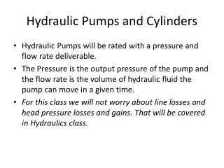
Hydraulic Cylinders and Cushioning Devices. Introduction. Hydraulic cylinders and hydraulic motors perform a function opposite to that performed by a pump. They extract energy from a fluid, and convert it to mechanical energy to perform useful work. Hydraulic Cylinder. Hydraulic System.

E N D
Introduction • Hydraulic cylinders and hydraulic motors perform a function opposite to that performed by a pump. They extract energy from a fluid, and convert it to mechanical energy to perform useful work. Hydraulic Cylinder Hydraulic System F x v Electric Motor Hydraulic Pump P x Q V x I T x ω Hydraulic Motor T x ω
Introduction • Hydraulic cylinders, also called linear actuators provide a force that drives an external load along a straight line. • Hydraulic motors, also called rotary actuators, provide a torque that drives an external load along a circular path. Hydraulic Cylinder Hydraulic System F x v Electric Motor Hydraulic Pump P x Q V x I T x ω Hydraulic Motor T x ω
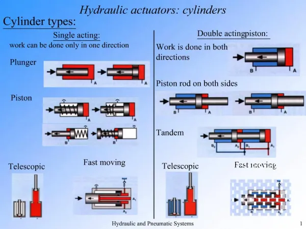
Single Acting Hydraulic Cylinders Piston Piston Seal Rod Extension Retraction Barrel Port • Push Action • Oil to extend Return by External Force • (e.g. Gravity) Graphic Symbol (P&ID Symbol)
Single Acting Hydraulic Cylinders • Push Action • Oil to extend, Spring for return • Pull Action • Oil to retract, Spring to extend
Double Acting Hydraulic Cylinders Piston Piston Seal Rod Extension Retraction Rod Seal Barrel Port B Port A • Oil to extend. Oil for Return Graphic Symbol (P&ID Symbol)
Double Ended Piston Rod Double Acting Cylinder Piston Piston Seal Rod Rod Seal Rod Seal Barrel Port B Port A • Oil to extend. Oil for Return Graphic Symbol (P&ID Symbol)
Cylinder Construction End Cap Tie Rod Barrel Front Cap Threaded Rod
Cylinder Mounting Methods Front Flange Rear Flange Clevis (Rear Pivot) Foot Bracket Side Lug Intermediate Trunnion
Cylinder Mounting Methods Front Flange Direct Rear Clevis (Rear Pivot) Foot Bracket Screwed Front Intermediate Trunnion
Combining Cylinders with Mechanical Linkages: Oscillatory motion with thrust amplification or reduction First Class Lever Second Class Lever Third Class Lever The three combinations are inverted slider crank mechanisms
Combining Cylinders with Mechanical Linkages:Straight line motion with thrust amplification or reduction 2:1 Motion Multiplier (Rack and Pinion) Two direction straight line Thrust Reducer (Six Bar Mechanism)
Combining Cylinders with Mechanical Linkages:Continuous Rotary Motion Continuous Rotation (Double Ratchet) Fast Rotary Motion (Screw and Nut)
Combining Cylinders with Mechanical Linkages:Motion Transfer Transfer to Distant Point (Pantograph)
Cylinder Alignment:Spherical Bushings and Spherical Bearings • Much effort has been made by manufacturers of hydraulic cylinders to relieve or eliminate the side loading of cylinders created as a result of misalignment. It is almost impossible to get perfect alignment and since the alignment of the cylinder has a direct bearing on its life, the efforts have been well worth while. • A spherical bushing or a spherical bearing is commonly used to deal with misalignment. This approach may not be able to take the loads that the cylinder is capable of producing. It can act as a complete hinge in one direction only, while being limited to a maximum misalignment of five degrees in the other directions. Spherical Roller Bearing Spherical Bushing
Cylinder Alignment: Universal Joints • A universal joint alignment accessory may be used. It allows fifteen degrees of angular misalignment on each side of center. It also provides more load carrying capabilities. • It is recommended that not more than a thirty degree maximum misalignment angle be used on the pins
Cylinder Force, Velocity and Power Piston Rod • Extension Stroke • Retraction Stroke Port Port
Cylinder Loading Through 1st class lever • As the lever rotates an angle ϴfrom its initial orientation, the cylinder rotates an angle фcyl and the load rotates with an angle фload Neglecting friction and dynamic loading (small values compared to forces from the cylinder thrust and load), then taking the moments around the pivot, O, we have L1 L2 ϴ O Fcyl • For small values of ϴandфcyl , and фload sin ϴsin фcyl ≈ 0, and sin ϴsin фcyl ≈ 0 Fload ϕload ϕcyl • Assuming no change on the load orientation, фload =0
Load Displacement Through 1st class lever • Assume no change on the orientation of the load, and using the conservation of energy (FcylΔcyl = FloadΔload), we have from the previous equation for small values of ϴandф L1 L2 ϴ O Fcyl Fload ϕ
Cylinder Loading Through 2nd class lever • Using the previous assumptions, with no change on the load orientation, we have we have • For small values of ϴandф, sin ϴsin ф ≈ 0, and L2 L1 ϴ O Fcyl Fload ϕ
Cylinder Loading Through 3rd class lever L1 L2 • In this case, we have • For small values of ϴandф, sin ϴsin ф ≈ 0, and ϴ O Fcyl Fload ϕ
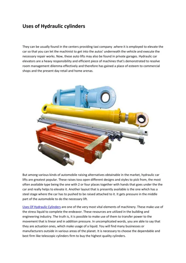
Buckling and Telescopic Cylinders • Buckling occurs when the rod of the cylinder bend or bows sideways under the action of compressive load. The longer and lighter the cylinder rod, the more likely it is for it to buckle. When selecting a cylinder from catalog, it is important to calculate the buckling loads. • Telescopic cylinders allow a longer cylinder stroke without buckling. These cylinders have from 2 to five telescopic sections with each section sliding inside a larger section. They are used for lifting platforms, tipping platforms and other commercial vehicle applications.
Hydraulic Cylinders Cushions • Double acting cylinders sometimes contain cylinder cushions at the end of the cylinder to slow down the piston near the ends of the stroke. This prevents excessive impact when the piston is sopped by the end caps. • Deceleration starts when the tapered plunger enters the opening in the cap. This restricts the exhaust flow from the barrel to the ports. During the last portion of the stroke, the oil must exhaust through an adjustable opening
Hydraulic Cylinders Cushions • The cushion also incorporates a check valve to allow free flow to the barrel during the piston’s reversed stroke. • The maximum pressure developed by cushions at the end of the cylinder must be considered, since excessive pressure buildup would rupture the cylinder. • Refer to example 6-6 in the textbook, which illustrates how to calculate this pressure.
Hydraulic Shock Absorbers • A shock absorber is a multiple orifice hydraulic device. When a moving load strikes the bumper of the shock absorber, it sets the rod piston in motion, which pushes the oil through the a series of holes from the inner, high pressure chamber, to the outer, low pressure chamber. • The resistance of the oil flow caused by the holes creates a pressure that acts against the piston to oppose the moving load.