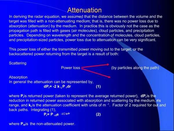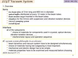
LCGT seismic Attenuation System
LCGT seismic Attenuation System. DRADF DRAFT DRAFT DRAFT. The LCGT-SAS Seismic Attenuation System. is a modern, simplified and improved version of the Virgo Superattenuators. Two tunnel solution.

LCGT seismic Attenuation System
E N D
Presentation Transcript
LCGT seismic Attenuation System DRADF DRAFT DRAFT DRAFT
The LCGT-SAS Seismic Attenuation System • is a modern, simplified and improved version of the • Virgo Superattenuators
Two tunnel solution • LCGT SAS is mounted between two tunnels due to the restrictions from the reserved space for the cryostat
Alternatives • The alternatives: • A space frame around the cryostat • Would have hampered the installation of the cryostat • Would have been a weaker support • Hooking the IP support point from the ceiling of a larger cave • Would have been difficult dangerous and weaker
Two tunnel solution • The two tunnel solution requires less rock removal, it is marginally cheaper and much more stable (mining-wise, seismically, and mechanically)
LCGT SAS wire length • The 2.2 m wire length between attenuation filters is determined by the mining requirements : • Minimum 5 m between tunnels • Space needed between the curved cave ceiling and crane straight beam • It is not determined by the attenuation requirements of LCGT 2.2 m 5m min
LCGT SAS • It is a prototype for third generation GWIDs • Mitigates the technical problems and costs associated with digging large caverns 2.2 m 5m min
LCGT SAS damping strategy • Mode damping is vital for easy locking of the interferometer • One extra filter is added at the beginning of the chain to provide passive Eddy current damping for the attenuation chain internal modes.
LCGT SAS damping strategy • Like in TAMA or Virgo accelerometers are foreseen for the inverted pendulum table for active attenuation • In LCGT only a backup
LCGT SAS pre-attenuation strategy • LCGT SAS has an Inverted pendulum-top filter • pre-attenuator stage, to deal with: • Microseismic noise • Tidal movements • Performs the same functions of the LIGO three active stages.
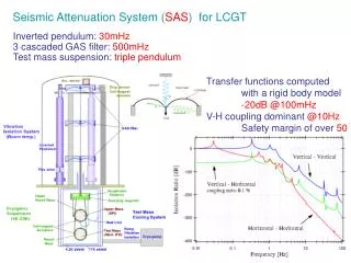
Attenuation strategy • Topologically LCGT-SAS is a Virgo-clone with two less filters than Virgo • OK because better seismic weather underground • LCGT SAS is expected to have same or better attenuation capabilities than Virgo
Thermal Noise Measured Upper Limit Passive attenuation measurements/CITF F. Frasconi - INFN Pisa
LCGT SAS attenuation strategy • Because of the longer wires the attenuation should start at 41% lower frequency than Virgo • LCGT SAS has one more attenuation stage than Advanced LIGO
Payload strategy • The payload is defined to be 300 kg • For Cryogenic payload development see separate presentation • Three options for warm payload: • Initial: 10 kg test masses • Advanced: 40 kg test masses • Heavy: 80 kg test masses 100 kg 100 kg 100 kg
Payload strategy • Bottom filter supporting: • Intermediate mass (1 wire on GAS) • Intermediate recoil mass (4 wires) • Intermediate mass supporting: • Test mass (4 fibers) • Coaxial recoil mass (4 wires)
Payload strategy • Virgo Design • Uncontrolled test masses • Controlled at lock acquisition • Magnetic actuators • Need to avoid Eddy current perturbations on controls • Dielectric masses
100 kg • Simple brick-like intermediate mass • Simple box like intermediate reaction mass • Virgo style Recoil mass surrounding test mass 100 kg 100 kg
Fused silica or Pyrex structures • Fused Silica parts bonded with glass frit or UV epoxy • Possibly Initial LCGT in metal
Test mass evolutionin case of delay of cryogenics Test mass 10 kg 40 kg 80 kg Recoil mass 80 kg 60 kg 20 kg
Auxiliary optics • LCGT designed with recycler telescopes in mind • Dedicated low attenuation towers for individual mirrors
Auxiliary opticsexternal structure • Inverted pendulum table on space frame surrounding vacuum chamber
Auxiliary optics payload • 10 kg mirrors from LIGO • Coaxial recoil mass in tandem because • No side occupancy for folded beams • Transmitted beam clearance