Download
1 / 23
230 likes | 761 Vues
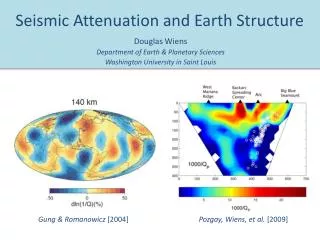
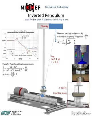
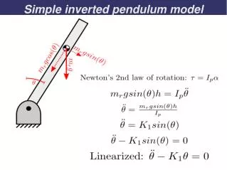
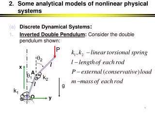
Inverted Pendulum Control for KAGRA Seismic Attenuation System. D2, Institute for Cosmic Ray Research Takanori Sekiguchi. Contents. Introduction of IP controls IP control model and simulation Current status of IP control experiment Summary. *IP = Inverted Pendulum.

E N D
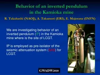
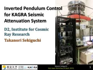
Inverted Pendulum Control for KAGRASeismic Attenuation System D2, Institute for Cosmic Ray Research TakanoriSekiguchi
Contents Introduction of IP controls IP control model and simulation Current status of IP control experiment Summary *IP = Inverted Pendulum
Suspension Local Controls Target: Damping of mechanical resonances Drift control at low frequencies Purpose: Reduction of RMS motions for lock acquisition Quick recovery after large excursion (e.g. EQ) Stable operation of the interferometer Rough idea of the requirement from MIF:
IP Local Control Top stage X, Y, Yaw motions are controlled. Drift control of IP & active damping of resonances(below 1 Hz) Sensitivity of sensors
Starting Point Starting from 1-D suspension model with simplified system Check controllability with combined sensor (LVDT & geophone) Simple suspension model Pre-isolator Prototype in Kashiwa ≡
Control Model Geophone senses top stage velocity LVDT senses relative displacement between top & ground Geophone for damping (>0.1 Hz), LVDT for drift control (<0.1 Hz) Sensor Noise (Calibration of the sensors are included in “suspension” block)
Filter Design Crossover frequency: 0.03 Hz Unity gain frequency: 0.8 Hz (phase margin: 60 deg.) Open-loop transfer function Gain boost at micro seismic peak High pass filter to reject glowing-up noise at low frequencies Chebychev filter for steep cut-off around micro seismic peak
Frequency Response to Seismic Motion Resonance is damped Active Isolation at micro seismic peak No seismic reinjection above 5 Hz
Noise Budget @Kamioka in Normal day Geophone Noise RMS dis.: 1.5x10⁻⁶ 2x10⁻⁶ m (@0.01 Hz) RMS vel.: 1.5x10⁻⁷ 2x10⁻⁷ m/s
Noise Budget @Kamioka in Stormy day RMS dis.: 2x10⁻⁵ 6x10⁻⁶ m (@0.01 Hz) RMS vel.: 2x10⁻⁶ 5x10⁻⁷ m/s
Summary We investigate IP controls with combined vibration sensors (LVDTs and geophones). Sensor noise (especially, geophone) is dominant with quiet environment in Kamioka mine. Low frequency vibration (<10 mHz) should be stabilized by other ways (global control).
Current Status of Pre-Isolator Prototype in Kashiwa IP is currently tuned at 80 mHz. LVDTs and geophones are installed and calibrated. X, Y, θ motions constructed by LVDTs and geophones resemble very well. Measured Y displacement by LVDT & geophone With excitation from virtual Y actuator Next step: Apply X control with combined sensors
Why Local Controls Are Necessary? Multi-suspension system has many mechanical resonances to be damped. Low frequency oscillators are sensitive to disturbance like temperature change, and drift easily. Local controls are required for lock acquisition and stable operation of the interferometer
Requirement For Lock Acquisition: Small RMS velocity and rotation angle of the mirror: Rough idea of the requirement: Short damping time of the mechanical resonances (within ~min.) During Operation: Actuation forces on the mirrors must be within the actuator range.(e.g. ~0.1 μm displacement level is allowed for test masses) 10 times smaller local control noises than other fundamental noises in the observation band.
Control Topology Top Stage LVDT: Drift control Geophone: Damping of pendulum modes Intermediate Mass Damping of residual resonances Alignment control Optical Lever Damping angular resonances? DC alignment signal
Control Topology X, Y Damp: GEO, OSEM DC: LVDT Z Damp: LVDT, OSEM DC: LVDTs on GAS Pitch, Yaw Damp: OSEM DC: Oplev Roll Damp: OSEM
Resonances of Pendulum modes Resonances at low frequencies contribute to RMS Damped by magnetic damper, but not perfectly Simulated Mechanical TF of Type-A SAS Pendulum mode @micro seismic peak
Pole Plot [variable gain] Too small gain unstable by LVDT control (~0.2 Hz) Too much gain unstable by geophone control (~0.01 Hz) Pole plot with variable gain of geophone control (gain 0 to 5, Blue: gain = 1)
Noise Budget @Kamioka in Normal day Geophone Noise
Noise Budget @Kamioka in Stormy day