Download
1 / 18
180 likes | 381 Vues
Time Triggered Programming - Patrick Gu. Control Systems of an Inverted pendulum - Rohan Bali. Mentor – Taylor Johnson. Time Triggered Programming Languages in Controls. What is Time Triggered Programming?.

E N D
Time Triggered Programming - Patrick Gu Control Systems of an Inverted pendulum - Rohan Bali Mentor – Taylor Johnson
What is Time Triggered Programming? Problem: Given any control system implemented in code, there is some processing time constraint, often requiring tedious code optimization during modeling. Current Design Process: Software Engineering Part 1: Create corresponding code. (manually, usually) Control Design: Create the control schemes and laws, mathematically. Hardware Implementation: Link our created code to hardware. Software Engineering Part 2: Optimize code to be within time constraints.
Solution: A time-triggered programming language automates the second task of the software engineer, leaving less work for the software engineer. Hypothetical Design Process: Control Design: Create the control schemes and laws, mathematically. Software Engineering: Create corresponding code. Time-Triggered Language: Optimize code to be within time constraints. Hardware Implementation: Link our created code to hardware.
Pro • Guarantees timing, allowing for more complicated control setups. • Automatic code generation, where not previously allowable. • Decreases errors, since code optimization may unintentionally introduce errors • Con • Can not handle interrupts except in cases of high frequency measurements, due to abstraction.
The First Time Triggered Programming Language: Giotto Giotto continually echoes a process periodically to guarantee timing. • Logically 0 Communication Time and Computation Constraints • Port Usage • -Input and Output Ports • -Private Ports/States • -Driver Guarding • -Sharing Ports and Timing • Modes • -Sharing t Henzinger, Thomas A., et al. “Giotto: A Time-Triggered Language for Embedded Programming”. From Proceedings of the IEEE 91 (1), pp. 84-99, 2003.
completion event release event Logical Execution Time (LET) termination event { Logical active { running running Physical release start preemption resume completion termination The Basis of Time Triggered Programming: LETs • Properties of LETs • Private Memory Space • Any Number of Processes (no Internal Synchronization) • Synchronization with Release and Termination Events Ghosal, Arkadeb, et al. “A hierarchical coordination language for interacting real-time tasks”. From International Conference On Embedded Software, 2006.
t1 reads 2nd instance of c1 t1 reads 2nd instance of c4 t1 updates 4th instance of c2 c4 c4 c4 c4 c4 c4 c3 c3 c3 c3 c3 Four communicators c1, c2, c3 and c4 with access periodicity 2, 3, 4 and 3 respectively. c2 c2 c2 c2 c2 c2 c1 c1 c1 c1 c1 c1 c1 c1 c1 0 1 2 3 4 5 6 7 8 9 10 11 12 13 14 15 16 17 The Second Iteration of Time-Triggered Programming: Hierarchical Timing Language (HTL) Communicators -Read/Write Time Precedence -Indirect Communication Mode -Direct Communication -Module Network -Mode Refinement LET for task t2 LET for task t1 A communicator is a variable (with a fixed data type) and can be accessed (i.e. read from and write to) only at specific time instances (denoted as communicator period).
Current State of the Project Task: Conversion of the HTL E-Machine from OSEK to NXTOSEK E-Machine: A program that “simulates” a machine OSEK: Open Systems and the Corresponding Interfaces for Automotive Electronics. This allows the use of uploaded code into specific kinds of vehicles. NXTOSEK: An extension of OSEK, that fuses together an OSEK platform with an automotive engine (TOPPERS/ATK) and a C/Assembly Language interpreter (LEJOS NXJ). Designed specifically for use with LegosMindstorm, our preferred form of testing.
Future State of the Project • First Task: Debugging the code. • Second Task: Writing of a test program. We are largely interested in the efficiency of running an HTL program, so we want a simple code. • Third Task: Testing. HTL must be viable, power-wise, in order for it to be used on a wide scale.
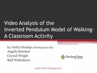
Outline • Goal • Evaluate pendulum behavior under different conditions. • Design multiple inverted pendulum system – This would have multiple pendulums communicating with each other, thus the constraints on a pendulum’s state variables would be modified real time depending on the position of the other pendulums.
Motivation • The principal of an inverted pendulum has various real world applications. The understanding of a similar problem is built in the technology of Segway. • The understanding of this can be applied to other controls problems with similar structure, for instance, traffic control systems.
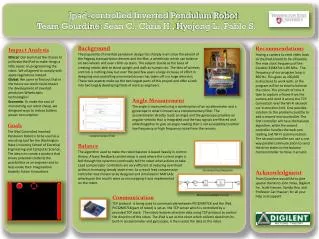
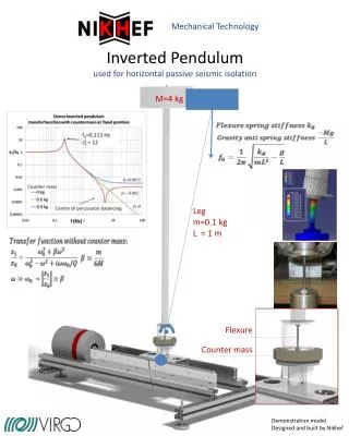
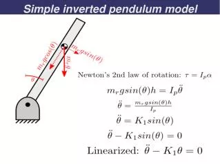
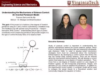
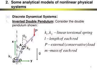
The Inverted pendulum • There are four state variables, the cart • position x, cart velocity x˙ , pendulum angle θ, and • pendulum velocity θ˙ • The physical system – DC motor • driven cart and a pendulum attached to the • cart • Goal - keeping the angle θ • of the pendulum at 0◦ measured from the vertical. • Moving the cart to a set point xs along the x-axis
How It Works • All state variables work under constraints • Controlled using the simplex architecture • Three controllers used in this architecture. • A safety controller - Stabilizes the system from • the largest set of initial conditions . Poor • Performance • A baseline controller- Cannot stabilize from such a wide set of initial conditions. Better performance than the safety controller. • An experimental controller – Smallest set of stabilize initial conditions . Best performance.
Future Work • Getting multiple pendulums to communicate between each other. • Thus the constraints on their state variables would be modified real • time. • Controlling the above system with a limited number of motors • and analyzing the stability of the system under those conditions. • Finding where such a system would breakdown and coming up with • solution to solve the problem.