Optoelectronics, a global telecom carrier’s perspective
320 likes | 478 Vues
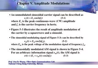
Optoelectronics, a global telecom carrier’s perspective. TWEPP 2008, 16.09.08 Dr Jeremy Batten jeremy.batten@cw.com. C&W Optical Network Optical fibre transmission and DWDM review 10 Gb/s: current standard 40 Gb/s developments and beyond Optical wavelength switching Summary.

Optoelectronics, a global telecom carrier’s perspective
E N D
Presentation Transcript
Optoelectronics, a global telecom carrier’s perspective TWEPP 2008, 16.09.08 Dr Jeremy Batten jeremy.batten@cw.com
C&W Optical Network • Optical fibre transmission and DWDM review • 10 Gb/s: current standard • 40 Gb/s developments and beyond • Optical wavelength switching • Summary DWDM – Dense Wavelength Division Multiplexing
C&W Optical Network BREADTH AND DEPTH
C&W OPTICAL NETWORKRICH HISTORY • 1860s One of the oldest telecoms companies • Subsea cable operator linking Britain internationally • Eastern telegraph company • 1928 Merger with Marconi Wireless: Cable & Wireless • 1947 Nationalisation • 1981 Privatisation • 1983 Mercury joint venture license to compete in UK • 2005-present UK consolidation (Energis, Thus?) • Network presence in 153 countries, Incumbent in several ex-UK territories • 4000 employees
C&W OPTICAL NETWORK SERVICES and GLOBAL INFRASTRUCTURE • Coverage: UK, Europe, Asia and US + multiple in-country operations • Services: IP Virtual private networks, wholesale voice, managed hosting, global bandwidth, IP peering 1+2 => Demands high-capacity optical networks • Multiple DWDM systems UK – fibre duct owned, • Europe, East US and Singapore – leased fibre on which DWDM deployed • US, Japan, Hong Kong – leased wavelength • Rest of world – leased sub-wavelength • Under-sea cable systems (Apollo transatlantic)
C&W OPTICAL NETWORK NETWORK ARCHITECTURE Consolidation Sites Concentration Sites Customer Sites Core Sites Service Distribution Layer Multi- IP/MPLS P Service Aggregation service ROUTER Layer PE Service Aggreg Multi- Core E P -ation service Layer C PE PE Multi- IP/MPLS P service ROUTER PE ‘last mile’ ‘mid mile’ MSPP OXC E T MSPP MSPP N Transport Core MSPP Backhaul Layer C W D M C W D M INTERFACE TO OPTICAL NETWORK E Metro DWDM Metro DWDM T M N D W D Access
C&W OPTICAL NETWORK Deployed terrestrial and subsea DWDM systems • C&W deployed systems. Subsea systems are joint ventures 1 Tb/s over 1000km Terrestrial systems doubling every ~1.5 years
C&W OPTICAL NETWORK Typical system characteristics • Scalability – 100 wavelengths • Reach – up to 2000km • Flexibility • Reconfigurability • Tunable optics (network side, 80 wavelengths) • Pluggable optics (client side, 850/1310/1550nm) • Power 2kW per 600mm x 600mm x 2.2 rack • Expectation that 1 Tb/s should occupy ~2 racks
Optical fibre transmission and DWDM* REVIEW*Dense Wavelength Division Multiplexing ITS NOT RADIO!
Optical fibre transmission and DWDM review OPTICAL IMPAIRMENTS • Attenuation • Chromatic dispersion • Polarisation mode dispersion • Non-linear effects
Optical fibre transmission and DWDM review ATTENUATION • Silica glass fibre absorption – Raleigh scattering -4, OH ion peaks and intrinsic high and low boundaries • Erbium Doped Fibre Amplifiers (EDFA) and Raman amplifiers commonly deployed to mitigate attenuation 0.18dB/km 25dB gain ->100km Intra-office 850nm Inter-office 1310nm Long haul DWDM 1530nm-1560nm
Optical fibre transmission and DWDM review CHROMATIC DISPERSION • Two ITU standardised fibre types are widely deployed: • G.652 – dispersion zero near 1310 nm; ~19 ps/nm.km at 1550 nm • G.655 – non-zero dispersion shifted, dispersion zero just below 1500 nm, ~5 ps/nm.km at 1550 nm • Compensating fibre is widely used on long haul systems • At 10 Gb/s the bit duration is 100 ps: ~20 ps of dispersion can be tolerated ITU: International Telecommunications Union
Optical fibre transmission and DWDM review POLARISATION MODE DISPERSION (PMD) • Polarisation states propagate at different speeds due to physical imperfections in fibre • Typically better than 0.2 ps/km but can be much worse • Generally not a problem for 10 Gb/s transmission but significant for 40 Gb/s
Optical fibre transmission and DWDM review NONLINEAR EFFECTS • Many types: self phase modulation, cross phase modulation, four-wave mixing • All strongly dependent on optical power density in fibre • Balance benefits of better OSNR with increased nonlinear effects as power is increased
Optical fibre transmission and DWDM review WAVELENGTH MULTIPLEXING
10 Gb/s The Industry standard
10 Gb/sINDUSTRY STANDARD • On-Off keyed Nonreturn-to-Zero (NRZ) • Continuous wave laser, external modulator • Full C-band tunability • pluggable client (variable reach, 850nm/1310nm) • Forward Error Correction (7% overhead, G.975/G.709) • 50 GHz multiplexing grid (0.2 b/s/Hz) • 1000-2000km range • Reconfigurable intermediate node add/drop to/from either direction (2 degree ROADM) • 35W per transceiver with client and network side optics
10 Gb/sALTERNATIVE APPROACHES • Full electronic chromatic dispersion compensation • Return-to-Zero (RZ) and Soliton - reach • Advanced amps (Raman) – optical bandwidth, longer single span • Photonic Integrated Circuits InP– 10*10 Gb/s on a chip: cheaper, more frequent, regeneration avoids impairments by reducing regeneration spacing (Infinera)
40 Gb/s READY FOR DEPLOYMENT
40 Gb/s CLIENTS • High end routers • Tb/s IP routers operating at 10 Gb/s require many parallel links • Problems: load sharing, routing tables, management, power consumption • Solution: 40 Gb/s now, 100Gb/s later • 4 X 10 Gb/s -> 40 Gb/s multiplexers for higher density
40 Gb/s REQUIREMENTS • Must co-exist with current deployed 10 Gb/s • Existing link engineering rules for: • amplifier gain and physical spacing • attenuation • chromatic dispersion • polarisation mode dispersion • 50GHz filter spacing • CD tolerance *16 worse, PMD tolerance *4 worse compared with 10 Gb/s
40 Gb/s MODULATION FORMATS INTENSITY MODULATION PHASE MODULATION ON-OFF KEYING (WITH “MEMORY”) CORRELATIVE CODING DQPSK DPSK NRZ RZ 8DPSK SOLITON DUO-BINARY POLARIZATION MODULATION FREQUENCY MODULATION
40 Gb/s DUO-BINARY Mach-Zehnder modulator
40 Gb/s DIFFERENTIAL PHASE SHIFT KEYING - DPSK Direct detection
40 Gb/s COMPARISON Comparison of duo-binary and differential phase shift keying modulation with NRZ OOK
BEYOND 40G100 Gb/s • Client is 100 Gb/s Ethernet; standardisation not complete • Plenty of ideas but no consensus on best approach • Compatibility on with current systems preferred • Field trials initiating • 100 Gb/s WILL arrive…one example (Stratalight) Polarisation multiplexed QPSK
OPTICAL SWITCHING EVOLUTION NOT REVOLUTION
Optical SwitchingOPTICAL ADD/DROP MULTIPLEXING • Move from point-point links to optical add-drop nodes (OADM) reduces electrical regeneration (O-E-O)
Optical Switching RECONFIGURABLE OADM – 1st GENERATION Programmable blocker enables reconfiguration of wavelengths Blocker technology mature (LCD, 2D-MEMS) MEMS: Micro electro-mechanical systems
Optical Switching BLOCKER SCALABILITY PROBLEM Number of blockers per DWDM direction (degree) increases as n2-n, so impractical beyond 3 directions
Optical Switching WAVELENGTH SELECTIVE SWITCH (WSS) • WSS scales linearly with number of directions • 100GHz/40 channel WSS being deployed for 3 and 4 degree nodes, 50GHz target. • 9 output ports typical • 3D MEMS (JDSU…) WAVELENGTH SELECTIVE SWITCH
SUMMARYTHANK YOU! • 10Gb/s very mature • 40Gb/s ready for deployment • 100Gb/s has no industry consensus at present • Development of WSS enable flexible, reconfigurable networks • In the next 3 years general deployment 2 Tb/s meshed optical networks -> an exciting prospect for optical carrier networks!