Download
1 / 12
120 likes | 239 Vues
Explore the scenario development, approaches, funding, and research efforts at ITER for creating advanced fusion reactor scenarios. Learn about the progress in modeling, code validation, and understanding ITER performance parameters. Various scenarios, from baseline inductive to low-activation, are detailed, along with the modeling efforts for steady-state and non-activation scenarios. Recent ITER tasks and studies have improved understanding and performance predictions, including advancements in controlling plasma shape, stability, and profiles. Efforts by ITER internal and external partners contribute to achieving successful scenarios.

E N D
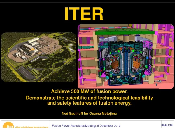
Summary of ITER scenario work T. A. Casper, D. Campbell, Y. Gribov, S.H. Kim*, T. Oikawa, A. Polevoi, J.A. Snipes, A. Winter, and L. Zabeo ITER Organization, Route de Vinon sur Verdon, 13115 St Paul Lez Durance, France *Monaco post doctoral program at ITER Acknowledgement: CORSICA support R. Bulmer, L.L. LoDestro, W.H. Meyer, and L.D. Pearlstein, Lawrence Livermore National Laboratory, P.O. Box 808, Livermore, CA USA 94550 ITPA IOS Meeting October 18 – 21, 2011 Kyoto, Japan
Modeling development for ITER scenarios: 1D transport + 2D equilibrium only (does not include other modeling work at ITER) • Scenario development that requires lots of parameter variation studies can and often is done with prescribed boundary evolution • Controller development and evaluation of engineering constraints require free-boundary with coupling to external systems • Scenarios of interest: • Full field scenarios at BT=5.3T in H-mode: • Baseline inductive: IP=15MA, Q=10, Pfus=500MW, to 400s duration • Advanced inductive or hybrid: IP=12.5MA, Q=5, 1000s duration • Steady-state: IP=9MA, Q=5, steady state – likely internal transport barrier • Low-activation scenarios: • DD at IP=7.5MA and BT=2.65T (half IP, BT) • Under development and of current interest for early experiments • Non-activation scenarios: H or He operations at reduced IP, BT • New interest for modeling to minimize CS coil demands • MHD evaluation for scenarios
Approaches leading to development of ITER scenarios • Internal at the IO • To develop internal ideas quickly and to test concepts • Build on and supplement work done outside the IO • Rapid response to committees and engineering design crises • Provide data to external research efforts, e.g. equilibria, profiles, constraints, etc. • Funded ITER tasks • Major efforts to scope out scenarios and/or design modifications – longer term • Contracts and must be competed among the DAs, a somewhat slow process • Volunteer – many efforts in DA programs typically coordinated by ITPA • Benchmarking with experimental data • Model and code validation • Modeling scenarios and detailed physics aspects – a few recent examples: • ISM coordinated effort in EU (Litaudon) – several codes and variety of topics • Individual efforts in scenarios with both DINA(Russia) and TSC(US) • Data sent for many physics studies: BOUT and ELITE edge stability, MHD evaluation, ECH study, RMP study, first wall evaluation, runaways, ripple loss, etc. etc. etc.
Recent ITER tasks and internal studies have advanced understanding of likely ITER performance: mostly CORSICA, DINA, and TSC • Current modeling includes latest modifications to ITER systems • coil and first wall geometry (may change again) • power systems and source design parameters • Increasing awareness of the divertor and first wall • Baseline inductive modeling – successful scenarios within operating space • Kessel, C.E. et al Nucl. Fusion 49 (2009) 085034 • Casper, T. et alaccepted Nuc. Fusion 51(2011) ; in Fusion Energy 2010 (Proc. 23rd Int. Conf. Daejeon, 2010) (Vienna: IAEA) CD-ROM file ITR/P1-19 http://www-naweb.iaea.org/napc/physics/FEC/FEC2010/html/index.htm • ITER tasks and efforts at the IO advanced modes: advanced inductive (hybrid) and steady-state scenarios (Gormezano, C. et alNucl. Fusion 47 (2007) S285-S336) • Kessel, C.E. et alin Fusion Energy 2010 (Proc. 23rd Int. Conf. Daejeon, 2010) (Vienna: IAEA) CD-ROM file ITR/P1-22 and http://www-naweb.iaea.org/napc/physics/FEC/FEC2010/html/index.htm • EU/F4E modeling effort currently in progress – results later today? • IO modeling effort started for hybrid mode: Sun Hee Kim presentation
Voluntary efforts have contributed significantly to ITER scenario development understanding – for example, a recent STAC report: TOPICS-1B: N. Hayashi et al., FinalReport on the ITER Task Agreement C19TD26FJ ITER_D_48DP5Z, 24 February 2011. CRONOS: J. Citrin et al., Nucl. Fusion 50 115007 (2010). Code-code comparison for steady-state scenarios Murakami, M. et al. Nucl. Fus. 51 103006 (2011).
CORSICA: Current emphasis for modeling at the IO is control of scenarios and development of the plasma control system (PCS) • 2D equilibrium + 1D transport predictive modeling code provides capability for controller simulations - applied to shape, vertical stability and profile control Crotinger, J.A. et al LLNL Report UCRL-ID-126284,1997 NTIS #PB2005-102154 • Full free-boundary GS solutions with various transport models - control of the evolution of plasma shape, vertical position and kinetic profiles • Simultaneously converges free-boundary equilibrium with transport at each time step – solutions always self-consistent • Calculates sources each time step - needed for feedback control applications • Monte-Carlo NBI with orbits and Toray-GA ECH/ECCD – previously used for DIII-D modeling and updated for ITER by Sun Hee Kim • ICH and LH capability recently added by Sun Hee Kim • DCON for time-dependent MHD stability assessment • Coupled with simulink control environment - independently executing and connected with RPCs (Meyer, W. et al, IAEA-TM, San Francisco June 2011) • Modular, customizable with interruptablework flows from interpretive scripting language interface – flexible and extensible environment
Elements in place at ITER for a PCS simulator: ITER control methods, JCT2001 controller, CORSICA implementation (b) Corsica realization of control simulator Casper, T.A. et al, FED 83 (2008) 552-556 (c) ITER shape and vertical position control (d) JCT2001 controller
CORSICA (or any code, e.g. DINA, TSC) free-boundary capabilities are required for controller modeling and development • CORSICA modes of operation (Casper, T.A. et al, FED 83 (2008) 552-556) • “backing-out”: fast, prescribed boundary evolution (no controller) with free-boundary evaluation at each time step to couple to external systems • Fast scenario development • Most engineering constraints evaluated, e.g. currents, forces, limits • Provides feed-forward waveforms for forward control • “forward” : full free-boundary shape and vertical stability evolution with controller – must run with dt ~ vertical growth time so lots of time-steps required • “hybrid”: free-boundary shape from controller in simulink with vertical stability internal to CORSICA – a new development done for speed in long pulse control simulations • Coupling to simulinkprovides a mechanism to test controllers (shape, vertical stability, and profile) during development • JTC2001 controller +VS1,VS3 both in simulink and internal to CORSICA • Interpretive interface with interrupts provides a mechanism for simulating event handling
CORSICA feedback-controlled evolution for baseline inductive case: IP=15MA, Q=10, 400s duration burn and Pfus=500MW • JCT-2001+VS1 controlled shape and vertical position, typically ~15,000 converged free-boundary solutions (700s discharge) • Performance results (a) • Coil currents (b,c) and forces (g) within operational limits • Controller voltage demands for vertical stability (d)and shape (e,f) (g)
Time-dependent evaluation (B,I)-limits and forces on coils * Simulation from fast current ramp with 17% reduction in I*B ~ different initial magnetization state * Power ramp to control power to divertor New diagnostic: UFC = utilization factor for superconducting coils – moved from equilibrium design to time-dependent
Summary/Future: the tools are in place and we are simulating a variety of controller aspects for ITER • Controller development - simulations will support these efforts • New controllers have been proposed for improving ITER performance • The Plasma Control System (PCS) conceptual design in progress Shape and vertical position • Significant efforts have been done for the baseline 15MA case • This needs to be extended to the alternative scenarios • Advanced inductive (hybrid) is being worked on • The Steady-state control will be done • Non- and low-activation scenario are being defined and developed • Kinetic control efforts for performance • Feed-back control of q (current profile) • Temperature and stored energy control • Burn control • Stabilization of islands • Event simulation, database and display testing
Additional concerns/emphasis for scenario modeling with regards to experiments • More experimental validation of codes used for ITER scenario analysis • Lots has been done to date, keep going • Concepts that need to be integrated into scenarios, e.g. divertor and stability • Effort to benchmark profile control between simulations and experiments • Specific studies of current ramp-up/ ramp-down scenarios under ITER-relevant conditions (i.e. potentially with a tungsten divertor) • Compatibility with tungsten divertor • Now using power ramp (5-20MW) during current ramp • Characterization of MHD during the current ramp-up in X-pointconfigurations • Fast, heated current ramp-up after X-point formation • Stability boundary lurking somewhere • Non-activation or low activation DD scenarios • IP/2 and BT/2 with ECH • Full BT at reduced IP ~ 10 or 12MA • CS coil limitations for “reduced” operation