Introduction to Orthographic Projection | CAD Engineering Lecture 5
Learn how to visualize and represent 3-D objects in 2-D through orthographic projection. Understand principle views and the glass box method to create detailed engineering drawings. Practice exercises provided.

Introduction to Orthographic Projection | CAD Engineering Lecture 5
E N D
Presentation Transcript
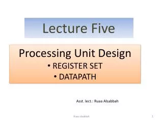
Lecture Five Dr. Tahseen Fadhil Abbas 2012-2013 Computer Aided Engineering Drawing CAD / CAD Engineering
INTRODUCTION TO ENGINEERING GRAPHICS Engineering graphics teaches you how to visualize and see all sides of an object in your mind. Being able to visualize in your mind will help you in several aspects of critical thinking.
ORTHOGRAPHIC PROJECTION INTRODUCTION An orthographic projection enables us to represent a 3-D object in 2-D(see Figure). An orthographic projection is a system of drawings that represent different sides of an object. These drawings are formed by projecting the edges of the object perpendicular to the desired planes of projection.
Orthographic projections allow us to represent the shape of an object using 2 or more views. These views together with dimensions and notes are sufficient to manufacture the part.
The Six Principle Views The 6 principle views of an orthographic projection are shown in Figure. Each principle view is created by looking at the object in the directions indicated in Fig. and drawing what is seen as well as what is hidden from view.
THE GLASS BOX METHOD To obtain an orthographic projection, an object is placed in an imaginary glass box as shown in Figure. The sides of the glass box represent the six principle planes. Images of the object are projected onto the sides of the box to create the six principle views. Object in a glass box.
The box is then unfolded to lie flat, showing all views in a 2-D plane. Figure below shows the glass box being unfolded to create the orthographic projection of the object. Glass box being unfolded.
THE STANDARD VIEWS When constructing an orthographic projection, we need to include enough views to completely describe the true shape of the part. The more complex a part, the more views are needed to describe it completely. Most objects require three views to completely describe them. The standard views used in an orthographic projection are the: FRONT VIEW TOP VIEW RIGHT SIDE VIEW The other views (bottom, rear, left side) are omitted since they usually do not add any new information.
The Front View The front view shows the most features or characteristics of the object. It usually contains the least number of hidden lines. The exception to this rule is when the object has a predefined or generally accepted front view. All other views are based on the orientation chosen for the front view. The top, front, and bottom views are all aligned vertically and share the same width dimension. The left side, front, right side, and rear views are all aligned horizontally and share the same height dimension
In Class Student Exercise 4 Missing lines Fill in the missing lines in the front, right side, and top views. Hint:The front view has one missing visible line. The right side view has one missing visible line and two missing hidden lines. The top view has five missing visible lines and two missing hidden lines.
Home Work 4Fill in the missing lines in the top, front, and right side views