Download
1 / 25
250 likes | 418 Vues
Evaluation of the Low Resistance Strip Sensors (Low-R) Fabricated at CNM. CNM (Barcelona), SCIPP (Santa Cruz), IFIC (Valencia) Contact person: Miguel Ullán. Outline. Motivation Proposed solution Design First batch Second batch tests Alternative technological solutions Conclusions.

E N D
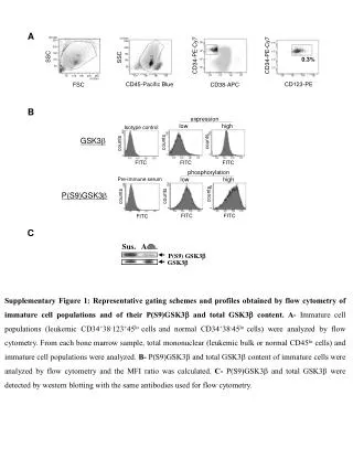
Evaluation of the Low Resistance Strip Sensors (Low-R) Fabricated at CNM CNM (Barcelona), SCIPP (Santa Cruz), IFIC (Valencia) Contact person: Miguel Ullán
Outline • Motivation • Proposed solution • Design • First batch • Second batch tests • Alternative technological solutions • Conclusions
“Far” end, no plateau. V(far) V(near) Motivation • In the scenario of a beam loss there is a large charge deposition in the sensor bulk and coupling capacitors can get damaged • Punch-Through Protection (PTP) structures used at strip end to develop low impedance to the bias line and evacuate the charge But… • Measurements with a large charge injected by a laser pulse showed that the strips can still be damaged • The implant resistance effectively isolatesthe “far” end of the strip from the PTP structure leading to the large voltages H. F.-W. Sadrozinski, et al. “Punch-through protection of SSDs in beam accidents” NIMA 658, Issue 1, pp. 46-50, 2011.
Proposedsolution • To reduce the resistance of the strips: “Low-R strip sensors” • Deposition of Aluminum on top of the implant: R□(Al) ~ 0.04 W/□ 20W/cm (Drastic reduction of strip resistance!) • Metal layer deposition on top of the implant (first metal)before the coupling capacitance is defined (second metal). • Double-metal processing to form the coupling capacitor • A layer of high-quality dielectric is needed between metals for the coupling cap. • Deposited on top of the first Aluminum (not grown) • Low temperature processing needed not to degrade Al: T < 400 ºC • Plasma Enhanced CVD (PECVD) process at 300-400 ºC • Triple-layer (oxide (1000 Å)+ Si3N4 (1000 Å) + oxide (1000 Å)): to avoid pinholes Yield
s Bias rail p d s Poly gate Implant Design • PTP design: • Design of experiments (DOE): varying p, s d • Wafer design: • 10 ATLAS-barrel-like sensors: “LowR sensors” • 64 channels, ~2.3 mm long strips • First metal connected to the strip implant to reduce Rstrip • Each sensor with a different PTP geometry (with polysiliconbridge) • 10 extra standard sensors for reference (no metal in implant). Identical design to the LowR but without metal strip on top of the implant
Bias pad0 V DC pad20 V ~ 0 V ~ 20 V PTP zone Bias pad0 V DC pad40 V Breakdown zone ~ 0 V ~ 40 V PTP zone Breakdown zone Firstbatch • PTP tests showed unexpected behavior: • Irreversible breakdown • Breakdown voltage independent of PTP structure geometry • at ~40 V in standard sensors and at ~20 V in LowR sensors • Oxide breakdown at a different place in the strip occurs before PTP is activated. • Thin oxides overlooked during fabrication • Only critical when PTP structures are present and tested Standard Low R
Secondbatch • New batch processed correcting these problems: • Thicker thermal oxide between implant and polysilicon Rbiasto avoid breakdown in standard sensors Thicker coupling capacitor in standard sensors (~1000 A) • Thicker oxide deposited between polysilicon Rbiasand Metal1 in LowR sensors to avoid breakdown in LowRsensors • In some extra sensors new metal mask (METAL-B) with no metal on top of polysilicon Rbiasarea to avoid the possibility of breakdown in that area • Some wafers have a reduced p-stop doping to make sure we have PTP • Design of Experiments:
General performance • IV, CV • Normal behaviour • VFD ~ 70 V • Higherleakagecurrentsaftercut(understudy) • Stripresistance • ~3 orders of magnitudereduction
General performance • Couplingcapacitance • Standard sensors: 31 ± 2 pF/cm • LowR sensors: 28 ± 1 pF/cm • ATLAS12 specs: > 20 pF/cm. • InterstripResistance • Interstripresistance > 1 GΩ
PTP structuretests • IV sweeps • Reversible breakdown (=> PT) • PTP voltage ~ 30 V • No evidentcorrelationbetween PTP distance and PTP voltage
PTP structuretests • PT effectiveresistance • Thereseems to be a correlationbetween final effectiveresistanceand PTP distance, althoughnotevidentwithinthesamewafer
PTP structuretests • Channel-to-channel • Punch-Through activation voltage (Vpt) is not stable among channels, geometry dependence seems to be low. • Final effective resistance value is stable among channels.
Laser tests • We use Alessi LY-1 “cutting” IR laser (1064 nm) to inject a largeamount of chargelocally in the sensor. • The total amount of chargeisabout 3x10⁷ MIPS, spread overfewmm. • Weinjectthe laser at eithernear and farlocations to assessthe sensor vulnerability to largecharges, since PTP(near) is superior to PTP(far). Injectionscheme Injectionregionsize
Laser scanresults Standard 70 umPTP • When laser isinjectednext to thenear DC pad, peakvaluesonVfar are similar to theonesonVnear. • As seenbefore, when laser isinjectednext to thefar DC pad, peakvaluesonVfar are higherthanonVnear. • No plateauup to ~180 V. • Strange“bump” at 140 V bias. • At 250 V, sensor currentvaluejumps.
Laser scanresults LowR 70 um PTP • ForLowRsensors, Vfar and Vnearpeakvalues are similar. • Peakvoltagesonbothnear and farendstend to stabilizeat ~180 V bias. But no evidentplateauisobserved. • Sensor leakagecurrentjumped at 250 V
Laser scanresults Standard 20 um PTP • When laser isinjectedonnearside, plateuisobservedafter 150 V bias. • No differenceisobservedbetweenVnear and Vfarwhenlaser isinjected in thenearside. • No plateauobserved in Vfarafterchargeinjectiononfarside • Peakvoltages are similar to previousresultson HPK sensorswith p-stop isolation. • Sensor biascurrentjumpedoneorder of magnitudewhen sensor biasreached 200 V.
Laser scanresults LowR 20 um PTP • Vfar = Vnear • A plateauisobservedforbothnear and far laser injectionsonVfar and onVnear. • Whenlaser isfiredonthenearside, plateuisseenafter 100 V bias. Forthefarside case, plateauisobservedafter 120 V.
Alternative technological solutions • Other methods to obtain LowR sensors being studied: • TiSi2: allows the use of high temperature steps after the oxide deposition oxide densification higher yield • Highly doped polysilicon: allows the growth of thermal oxide after it high quality oxide • back to “standard” process • A small batch of sensors currently being fabricated at CNM
TitaniumSilicide (TiSi2) • TiSi2 processing technology at CNM • Good formation of TiSi2 layer • Low sheet resistance: ~1.2 Ω/ • Densification at 900 ºC , 30 min • Self aligned process ( No mask) • TiSi2MiM capacitors fabricated • 98-100 % yield up to 100 V (not enough statistics: 1-2 cap failing out of 62 measured)
HighlydopedPoly-Si • Polysilicon layerdopedwithliquidsource (POCl3, “Phosphorylchloride”) in contactwiththesiliconimplant (substitutesthe metal layer) • High doping levelsreached at hightemperatures (1050ºC) and long times • Possibility to grow a thermal oxide on top of the polysilicon layer to formthecoupling capacitor • Muchhigherquality oxide • Althoughrisk of lowerbreakdownvoltages • Higherthermal load of theprocess • Risk of dopantprecipitateslater in theprocess • MIM capacitors • Goodconductance (~2-3 Ohm/sq) • 98-100 % yield up to 20 V • Breakdown @ 40-50 V (2000 A ox. thickness)
Conclusions & futurework • Low-resistancestripsensors (LowR) proposed to extendtheprotectionaffordedby PTP structure to theentire active area of the sensor • Implementationwith Aluminum layer in contactwiththeimplant to drastically reduce stripresistance • LowRsensors show similar general characteristics as standard sensors • PTP behaviourvariesfordifferentstructures(problems of firstbatchsolved), althoughstillsomefeatures to be fullyunderstood. • Laser tests show aneffectivereduction of theimplantvoltage at bothnear and farsides of thestrip, and forchargeinjection at eitherstripside. • New possibleimplementationsbeingtriedwithTiSi2 and polysilicon to assure a better coupling capacitor formation, and a more standard processing • Future work • Irradiations • Test new deviceswith TiSi2 and highlydopedPoly-Si
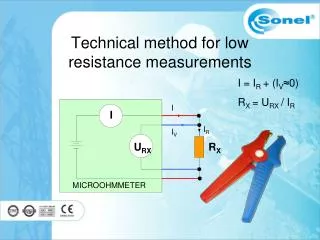
Interstripresistancemeasurement • HP4156 • Voltage sweep: -1 V to 1 V (P4) • Voltage step: 0.05 V • Bias voltage: -100 V (chuck) • Expected value: • Rinterstrip> 10 x Rbias @ Full depletion • Rbias: <2.5 – 3.0> MΩ • Rinterstrip= 2 / (∂INeighbour/∂Vtest) P1 Ground P2 Ground Vtest Ground P4 P3
Punch-Throughmeasurement HP4156 Voltage sweep: 0 V to 70 V (P4) Voltage step: 0.25 V Bias voltage: -100 V (chuck) • For Vbias < -100 V • Use K2410 for -300 V, -200 V bias Effective resistance: Reff= 1 / (∂Itest/∂Vtest) = Rbias // RPTP zone Vtest P4 P3