Download
1 / 14
140 likes | 304 Vues
Experimental and Numerical studies on Bulk Micromegas. SINP group in RD51 Applied Nuclear Physics Division Saha Institute of Nuclear Physics Kolkata, West Bengal, India. BULK MICROMEGAS. Details of BULK Micromegas used: . 10x10 cm 2 active area

E N D
Experimental and Numerical studies on Bulk Micromegas SINP group in RD51 Applied Nuclear Physics Division Saha Institute of Nuclear Physics Kolkata, West Bengal, India
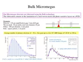
BULK MICROMEGAS Details of BULK Micromegas used: .10x10 cm2 active area .Amplification gap: 192 mm and 128 mm .Stainless steel mesh, wire diameter 18 mm, pitch 63 mm .Dielectric Spacer, diameter 400 mm, pitch 2 mm RD51 mini Week @ CERN
Motivation • BULK Micromegas with 128 m amplification gap – promising candidate for building TPCs • Recent interest – characterization of larger gap BULK Micromegas • Comparison of standard BULK with a BULK having larger amplification gap of 192 m - measurement of detector gain, energy resolution, transparency etc in argon based gas mixtures • Comparison of measured detector characteristics to numerical simulations using Garfield framework • A numerical study to determine the effect of dielectric spacers RD51 mini Week @ CERN
Experimental Set Up Gas Cylinder Purification System Residual Gas Analyzer Gas Mixing System Power Supply (High Voltage) (N471A) Gas Flow In Pressure Gauge Gas Chamber & Detector Gas Flow Out Pre-Amp (Model No. – 142IH) Filter Multi- Channel Analyzer Amplifier (ORTEC 672) Oscilloscope RD51 mini Week @ CERN
Numerical Simulation Simulation tools • Garfieldframework: to model and simulate two and three dimensional drift chambers • Ionization: energy loss through ionization of a particle crossing the gas and production of clusters —HEED • Drift and Diffusion: electron drift velocity and the longitudinal and transverse diffusion coefficients —MAGBOLTZ • Amplification: Townsend and Attachment Coefficient —MAGBOLTZ • Field: Electric Potential and Field – neBEM(nearly exact Boundary Element Method) Garfield + neBEM + Magboltz + Heed RD51 mini Week @ CERN
Measured Gain Vs. Simulated Estimate Amplification Gap: 192 m b) Gas: Argon 90% Methane 10% a) Gas: Argon 90% Isobutane 10% • Without penning effect, simulated gain is considerably lower • In Argon:Isobutane 90:10, we have chosen the penning transfer rate to be 80%, which is much higher than that used in ref [1] • In P10, the chosen penning rate, 25%, agrees well with ref [1] [1] ӦSahin et al 2010 JINST 5 P05002 RD51 mini Week @ CERN
192 mm vs 128 mm (Experiment and Simulation) Gain • Penning rate 25%, for 192 m, numerical value of gain agrees well with experimental one • At this penning rate, for 128 m, numerical value is lower than experimental data (preliminary) • Penning rate 80% for both detectors, numerical value of gain is lower than that of experimental data • A small change in amplification gap, changes simulated detector gain considerably. This effect is more prominent in 128 m RD51 mini Week @ CERN
Energy Resolution • At higher field ratio, 192 m shows better resolution than 128 m • Simulations follow the experimental trend, though the estimated value is lower • Higher estimation of electron transparency using wire model, affects the simulated value • The calculation of variation of gain needs further investigation • The energy resolution in P10 also shows the same trend RD51 mini Week @ CERN
Drift Field 100 V/cm Wire Model Cylindric Model Electron Transparency with field ratio Drift Field 2000 V/cm Wire Model Cylindric Model Equipotentials in the mid-plane of a mesh hole, in the thin-wire approximation of the mesh (left hand side) and using octagonal approximations of solid cylinders (right hand side). RD51 mini Week @ CERN
Effect of Spacer (Diameter 400 m, Pitch 2 mm, Amplification Gap 128 m) Electric Field b) without dielectric spacer a) in axial direction through different holes c) with a dielectric spacer d) a close-up of (c) RD51 mini Week @ CERN
Without Spacer With Spacer Without Spacer With Spacer Near spacer, electron drift lines get distorted – affect detector gain RD51 mini Week @ CERN
Signal and End Points of Avalanche Electrons With spacer, the signal amplitude is lower and it has a long tail. Readout pads around spacer are affected— likely to affect tracking efficiency To be further investigated soon … RD51 mini Week @ CERN
neBEM • All the calculation presented here have been carried out with V1.8.12 • One bug-fix • Increase in speed by 20-30% in the post-processing phase (evaluation of potential and field) • No compromise in accuracy • Future versions will focus on • Error estimation • Even faster execution • Solid modeling capabilities RD51 mini Week @ CERN
Summary • Maximum gain achieved with a larger amplification gap found to be similar/ slightly more than that with a smaller gap. • For higher gains and higher field ratios, larger gap yields better resolution. • Successful comparisons with simulation indicate that the device physics is quite well understood. Exact value of Penning rate for certain gases remains an issue, though. • Effects of spacers on gain, signal and distribution of electrons as they reach the anode, indicated significant changes occurring around the spacer. • In future, further studies to be carried out using Micromegas having a wider range of amplification gaps. Additional gas mixtures to be used, as well. • Other important features such as ion back flow to be studied. • A new version of neBEM released. Further developments expected soon. RD51 mini Week @ CERN