S T I
Programmation CN Langage ISO. S T I. Principe. Logiciel FAO. Programme Langage ISO. Programmation manuelle. Origine Programme. Origine mesure. Pour réaliser un usinage, la machine doit exécuter des déplacements du point courant par rapport à l’Origine mesure : Om.


S T I
E N D
Presentation Transcript
JLH Programmation CN Langage ISO S T I
JLH Principe Logiciel FAO Programme Langage ISO Programmation manuelle
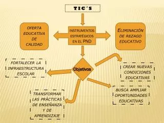
JLH Origine Programme Origine mesure Pour réaliser un usinage, la machine doit exécuter des déplacements du point courant par rapport à l’Origine mesure :Om Pour faciliter le calcul des points programmés et tenir compte de la géométrie du matériel employé (machine, outil, porte-pièce) une chaîne géométrique est construite. L’opérateur déclare dans le programme les coordonnées des points générés par rapport à l’origine programme OP. Origine porte-outil Point courant PREF Point générateur JAUGES OUTIL clic Origine Programme Origine porte-pièce POSITION PROGRAMMEE DEC 1
JLH 20 20 10 26 32 50 30 10 26 50 32 50 40 20 50 32 26 Origine programme 50
JLH Y 55 Y 25 15 45 55 X Z 10 30 80 Origine programme
JLH Coordonnées des points programmés • Repérer les points programmés sur le dessin • Calculer leur position par rapport aux axes de l’Origine Programme OP en cotes moyennes • Reporter leur coordonnée dans un tableau
JLH X • Y 4 45° 3 2 1 Ø50 Ø30 20 Coordonnées des points programmés Z
JLH PROGRAMME BLOC MOT Numéro de bloc Mot de fonction auxiliaire Mot de dimension Mot de fonction préparatoire Mot de fonction technologique Définitions Programme %100 N10 … N20 … N… N… ….. N100 G1 X30.4 F120 M8 N… N… ….. N340 M2 N… G… X… F… M…
JLH NUMERO DE PROGRAMME IDENTIFICATION INITIALISATION POSITION DEGAGEMENT OPERATION 1 POSITION DEGAGEMENT Structure programme
JLH OPERATION N POSITION DEGAGEMENT FIN DE PROGRAMME Structure programme
JLH Structure d’une Opération
JLH Fonctions ISO
JLH Fonctions G
JLH Fonctions G (suite)
JLH Fonctions G (suite)
JLH Fonctions M
JLH Principales actions
JLH Principales actions
JLH Vy max Vx max Fonction G0 Action : Déplacement en rapide du point A au point B. N5 G0 XB YB Y B Vx max Déplacement suivant X et Y à vitesse égale. Déplacement suivant Y à vitesse rapide. A X Conclusion : Le Déplacement ne suit pas une trajectoire rectiligne continue.
JLH F Fonction G1 Action : Déplacement linéaire en vitesse travail du point A au point B. Y N25 G1 XB YB F240 B A X
JLH F Fonction G2 Action : Déplacement circulaire sens anti-trigonométrique en vitesse travail du point A au point B. Y N110 G2 XB YB RC F240 C B A X
JLH F Fonction G3 Action : Déplacement circulaire sens trigonométrique en vitesse travail du point A au point B. Y N200 G3 XB YB RC F240 C A B X
JLH Exo G1 G2 G3
JLH A B C Fonction G64 SUIVANT Z A B N… G64 N… N… I… K… P… N… Xa Za N… Xb Zb N… Xc Zc (N=numéro du dernier bloc du profil) (N=numéro du premier bloc du profil) (I=surépaisseur de finition sur X) (K=surépaisseur de finition sur Z) (P=profondeur de passe) (Xa,Za=1er point limite du brut) (Xb,Zb=2eme point limite du brut) (Xc,Zc=3eme point limite du brut) P C K I Definition du brut Xa Za Xb Zb Xc Zc SUIVANT X Definition du brut Xc Zc Xb Zb Xa Za
JLH A B 5 4 3 2 1 C Exo G64 Surépaisseur en X = 0.5 Surépaisseur en Z = 0.2 Profondeur de passe = 1 PROFIL FINI PROFIL BRUT
Point 5 JLH A B 5 4 3 2 1 C Profil Fini PROFIL FINI Vc = 180m/min F = 0.1 mm//tr
JLH Fonction G83 Cycle de perçage avec débourrage (évacuation des copeaux) XY ER N… G83 Z… ER… P… Q… (Z=cote de fond du trou) (ER=cote de plan de retrait) (P=profondeur de passe) (Q=profondeur de la dernière passe) P Q Z
JLH Exo G83 N = 180t/min F = 0.1 mm//tr
JLH 1 6 1 6 Z Z 5 2 3 4 5 2 5 3 4 Y X 30 70 1 2 5 6 5 Y 80 10 50 10 3 4 X Surfaçage Fraisage
JLH Exo G81
JLH X X X Z Z Z Le profil obtenu = profil théorique Profil obtenu Profil théorique G40-G41-C42en tournage Sans correction de rayon G41 ou G42 Avec correction de rayon G41 ou G42
JLH Prise en compte du G40 Prise en compte du G40 G41-C42en fraisage Correction G41 : Profil à droite de l’outil dans le sens de l’avance Correction G42 : Profil à gauche de l’outil dans le sens de l’avance Prise en compte du G41 1 4 2 3 2 3 Prise en compte du G42 4 1 Points programmés 1, 2, 3, 4.
JLH Fonction G41 G42
Tout est dit… Tout est compris… Merci de votre attention.