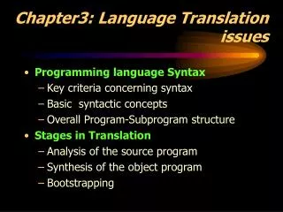
Chapter3
Chapter3. Digital Circuits. Preface. 5V. ‘ 1 ’. 2.5V. 0V. ‘ 0 ’. Threshold. ‘ 1 ’. 3V. 2V. ‘ 0 ’. ?. 2.5V. ?. 3V. 2V. High-state DC noise margin V OHmin -V IHmin. 5V. ‘1’. V OHmin. ‘1’. =4V. Digital Sender. 3V=. V IHmin. Digital Receiver. Abnormal. V ILmax. 2V=.

Chapter3
E N D
Presentation Transcript
Chapter3 Digital Circuits
Preface 5V ‘1’ 2.5V 0V ‘0’ Threshold
‘1’ 3V 2V ‘0’ ? 2.5V ? 3V 2V
High-state DC noise margin VOHmin-VIHmin 5V ‘1’ VOHmin ‘1’ =4V Digital Sender 3V= VIHmin Digital Receiver Abnormal VILmax 2V= ‘0’ VOLmax =1V Low-state DC noise margin VILmax-VOLmax ‘0’ 0V
3.1 CMOS and TTL Logic • Diode logic (DL) • Direct-coupled transistor logic(DCTL) • Resistor-transistor logic (RTL) • Resistor-capacitor transistor logic (RCTL) • Diode–transistor logic (DTL) • P-type metal–oxide–semiconductor logic (PMOS) • N-type metal–oxide–semiconductor logic (NMOS) • Cascode Voltage Switch Logic(CVSL) • Complementary Pass-transistor Logic(CPL) • Integrated injection logic (I2L) • Emitter coupled logic (ECL) also known as Current-mode logic (CML) • Positive emitter-coupled logic (PECL) • Low-voltage positive emitter-coupled logic (LVPECL) • Transistor–transistor logic (TTL) and variants(LS TTL) • Complementary metal–oxide–semiconductor logic (CMOS) • Bipolar complementary metal–oxide–semiconductor logic (BiCMOS)
■James L. Buie invented TTL logic circuits in 1961. ■Frank Wanlass invented CMOS logic circuits in 1963. ■The Texas Instruments 5400 family(1964) and 7400 family(1966)became an industry standard ■RCA CD400 family(1968) became an industry standard . A B
1.Logic Levels and Noise Margins CMOS Levels Voltage: VIHmin VILmax VOHmin VOLmax TTL Levels Output ‘1’ Output ‘1’ 5V Input ‘1’ 5V VOHmin=4.9V High-state DC noisemargin=1.4V Input ‘1’ VIHmin=3.5V VOHmin=2.7V Abnormal High-state DC noisemargin=0.7V VIHmin=2V VILmax=1.5V Abnormal VILmax=0.8V Low-state DC noisemargin=1.4V VOLmax=0.5V VOLmax=0.1V Input ‘0’ 0V 0V Output ‘0’ Input ‘0’ Output ‘0’ Low-state DC noisemargin=0.3V
2.Fanout P99 Table3-3 54/74HC00 Datasheet (NAND Gate) Driving capability IO II1 A ● Input(+) ‘1’ ‘1’ Output(-) II2 ‘1’ ? IIn ‘1’ Fanout=
Ex.3-1 Fanout1= CMOS driving CMOS P99 Table3-3 =20 VOHmin=4.4V IOH1=-20μA High-state DC noise margin1 VOHmin=3.84V IOH2=-4mA = Low-state DC noise margin1 =1.25V VOLmax=0.1V IOL1=20μA VOLmax=0.33V IOL2=4mA Fanout2= IIH=1μA =4000 IIL=-1μA High-state DC noise margin2=0.69V Low-state DC noise margin2=1.02V
Ex.3-2 CMOS driving LS-TTL Fanout= P99 Table3-3 P168 Table3-11 =10 IIH=20μA High-state DC noise margin=1.84V IIL=-400μA Low-state DC noise margin=0.47V VOHmin=3.84V IOH2=-4mA VOLmax=0.33V IOL2=4mA
Ex3-3 Fanout1= LS-TTL driving LS-TTL P168 Table3-11 =20 IIH=20μA High-state DC noise margin1=0.7V IIL=-400μA Low-state DC noise margin1=0.3V VOHmin=2.7V IOH=-0.4mA VOLmax=0.5V IOL1=8mA Fanout2= VOLmax=0.4V IOL2=4mA Ex3-4 =10 High-state DC noise margin1=0.7V LS-TTL driving CMOS Low-state DC noise margin1=0.4V
TTL Levels CMOS Levels 5V 5V VOHmin=4.9V High-state DC noisemargin=1.4V VIHmin=3.5V VOHmin=2.7V Abnormal High-state DC noisemargin=0.7V VIHmin=2V VILmax=1.5V Abnormal VILmax=0.8V Low-state DC noisemargin=1.4V VOLmax=0.5V VOLmax=0.1V 0V 0V Low-state DC noisemargin=0.3V TTL VOHmin<CMOS VIHmin Maybe cause logic confusing!
3.CMOS/TTL Compatible CMOS/TTL Compatible Levels 5V VOHCmin=4.9V Input TTL VOHTmin=3.84V High-state DC noisemargin Output CMOS VIHmin=2V Abnormal VILmax=0.8V VOLTmax=0.33V Homework: P175 3.1 3.20 3.22 3.57 VOLCmax=0.1V 0V Low-state DC noisemargin
VDD = +5.0V Q2 VOUT VIN Q1 3.2 CMOS Gates 1.Inverter(NOT Gate) Functional behavior VIN(V) Q1 Q2 VOUT(V) 0.0(L) off on 5.0(H) 5.0(H) on 0.0(L) off 5.0(H) 0.0(L) 0.0(L) 5.0(H) IN OUT Logic symbol Circuit diagram
VDD = +5.0V Q2 Q4 Z Q1 A Q3 2.Buffer Inverter is faster than Buffer! B A B B Z Circuit diagram A Z Logic symbol
VDD Q2 Q4 Z A Q1 B Q3 3.NAND Gate Functional table A B Q1 Q2 Q3 Q4 Z on on L L off off H × × on on off √ √ L H off H off off on H L on H H L on off on off L H H H L × √ A H L Z × √ B Logic symbol Circuit diagram
VDD Z A B 4.AND Gate NAND Gate is faster than AND Gate! A C B C C Z A Z B Circuit diagram Logic symbol
VDD VDD A A B B Z Z 5.NOR Gate and OR Gate NOR Gate is faster than OR Gate! Inverter C A A Z Z B B NOR Gate Logic symbol OR Gate Logic symbol
VDD VDD A A B B Z C Z D C D 6.AND-OR-INVERT and OR-AND-INVERT Gates OR-AND-INVERT Gate AND-OR-INVERT Gate
EN_L A B EN EN_L A B EN 7.Transmission Gate Features: ■Short delays between A and B ■Bidirectional Applications: ■Multiplexers ■Analog switch Transmission Gate Logic symbol
VOUT VOUT VT- VT+ 5.0 5.0 VT VIN VIN 2.1 2.9 5.0 2.5 1.5 3.5 5.0 Schmitt-Trigger characteristic 8.Schmitt-Trigger Input Ordinary inverter characteristic Logic symbol
Ordinary inverter Output Output produced by an inverter with 0.8V hysteresis
VCC Q2 EN OUT Q1 A EN A OUT 9.Tree-State Outputs EN=1 A OUT EN=0 Q1 and Q2 are off Output is in the floating state or high-impedance (Hi-Z). Application: ■Bus I/O Logic symbol
Hard Disk Driver Display 40bit 16bit SDRAM 40bit Floppy Disk Driver ROM CPU 24bit 16bit 25bit 8bit 40bit CDROM Printer Keyboard USB SD Card Network Scanner Game Joystick
Address Bus Floppy Disk Driver Data Bus Hard Disk Driver Display CDROM CPU ROM SDRAM Printer SD Card Control Bus Keyboard Just one device active at one time! Hi-Z to Low or High is slower than Low or High to Hi-Z.
VCC R A Z B Z A Q1 B Q2 10.Open-Drain Outputs Choice of value for the Pull-up resistor P139 Pull-up Resistor Logic symbol Applications: ■Driving LEDs ■Driving Multisource Bused ■Wired Logic
VCC A VCC B VCC C D Wired Logic VCC R Z1 Z2 Z Z3 E F
A ≥1 Z B 1 A Z A & Z B Summary(1) Three basic logic functions: AND,OR,NOT A A Z A Z Z B B Z=A AND B Z=A OR B Z=NOT A =A·B =A+B GB symbol GB symbol GB symbol
≥1 & Summary(2) A A Z Z B B Z=A NAND B Z=A NOR B A A Z Z B B GB symbol GB symbol
Truth Table A B Z Z 0 0 1 A A 0 = =1 Z Z Z=A B · 0 1 0 B B 1 0 1 1 0 1 1 0 1 Summary(3) A A Z Z B B Exclusive-NOR Gate Exclusive-OR Gate Z=A XNOR B Z=A XOR B =A B · GB symbol GB symbol
A ≥1 & A & ≥1 B B Z Z C C D D Summary(4) A A B B Z Z C C D D GB symbol GB symbol
VIN VIN VOUT 3.3 CMOS Dynamic Electrical Behavior 1.Speed of a CMOS device VIHmin ■Transition time VILmax ■Propagation delay The “on” transistor resistance Rise time andFall time The load capacitance Semiconductor Physics Input Capacitance Output Loading Multistage devices
2.Power Consumption Total Dynamic Power: Internal Power Dissipation: Load Capacitance Dissipation: Power-Dissipation Capacitance Power-Supply Voltage Transition Frequency Capacitance Load
3.4 Some problems of using CMOS ■Effects of Loading Loading an output beyond its Rated Fanout. ■Logic confusing ■Bad for Dynamic Characteristic ■Temperature of the device may increase ■Unused Inputs (Pulled up or Pulled down Resistor) Should never be left unconnected (or floating) ■ESD Electrostatic Discharge ■Latch-up Silicon-Controlled Rectifier (SCR) ■Current Spikes and Decoupling Capacitors
3.5 CMOS Logic Families HC and HCT AHC and AHCT VHC and VHCT FCT and FCT-T
3.6 Low-Voltage CMOS Logic and Interfacing Compatible Homework: P175 3.86 0.0 0.0 0.0 0.0 0.0