CHAPTER3 CROSS SECTION DESIGN
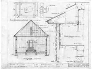
Cross section elements consist of the following: 1.Traffic lanes (carriage ways); 2.Shoulders; 3.Medians; 4.Curbs; 5.Side slopes. CHAPTER3 CROSS SECTION DESIGN. Fig. 4 shows these elements for 2-lane as well as multi-lane highways. 1.Traffic Lanes:

CHAPTER3 CROSS SECTION DESIGN
E N D
Presentation Transcript
Cross section elements consist of the following: 1.Traffic lanes (carriage ways); 2.Shoulders; 3.Medians; 4.Curbs; 5.Side slopes. CHAPTER3 CROSS SECTION DESIGN
Fig. 4 shows these elements for 2-lane as well as multi-lane highways.
1.Traffic Lanes: The number of traffic lanes depends upon the volume of traffic moving on the road (or expected to move on it in the future) and the level of service required which based mainly on capacity . To determine the number of lanes , the total traffic volume (ADT) is determined, DHV for future is calculated and compared with design capacity of a lane.
Example: A traffic count on an existing rural road 22 ft. paved width show that the existing ADT =2000 veh./hour of which 10% is truck traffic and 60% of traffic travel in the main direction during peak hour. Assuming that the road crosses a rolling area and future increase during a life time is 100% . It is required to determine: 1. DHV; 2.No. of lanes for speed 45-50 mph.
Solution: DHV = 0.15 ADT = 0.15 (2000) = 300 veh./hour Future DHV = 300 x 2 = 600 veh./hour T = 10 % T = 5 PC (2-lane rural) = 4 PC (multi-lane ) From Tab. , at 10 % Trucks Coeff. = 0.58 for 2-lane , Coeff. = 0.77 for multi-lane For 2-lane DHV (30 HV) = 600/0.58 = 1000 P/hr. DHV in heavier direction = 1000 x 0.6 =600 P/hr. DHV in both directions = 2 x 600 =1200 P/hr. Practical capacity of 2-lane for best ideal conditions at speed 45-50 mph =720 P/hr. 4-lane highway is selected for design (2-lane may be constructed for the first 10 years ).
2. Lane Width: The maximum width of a vehicle is 2.44 m. To allow at least 15 cm at each side of the vehicle as a clearance, so the minimum width of traffic lane is 2.75m (9 ft.). The clearance should be increased with increasing the design speed. The recommended width for all road types is 3.75 m (12 ft.) for any design speed, when DHV is more than 400 v/hr. . Tab.8 shows the minimum width of pavement for 2-lane rural roads caring DHV traffic <400 v/day.
3.Shoulders: The following are the most important advantages of shoulders: 1.They provide space for stopping due to motor trouble; 2.Provide enough space to avoid other faults and to reduce accidents; 3.Sight distance is improved in cut sections and curves; 4.It improves the capacity of the highway ; 5.Shoulder is a structural support to the pavement.
- Shoulder width: The minimum shoulder width is 10 ft. for multi-lane and 2-lane highways of DHV > 400 v/hr. While , for 2-lane highways with DHV <400 v/hr.the min. shoulder width should be as follows: 8 ft. for DHV 200-400 v/hr. 6 ft. for DHV 100-200 v/hr. 4 ft. for DHV < 100 v/hr. Shoulder slope ranges from 3-4 % for bituminous surface
4.Medians: Median is simply a separation between two opposing streams of traffic, its functions are: - reduce head light glare; -eliminate points of conflicts and hence to reduce probability of accidents; -offer a refuge between opposing traffic streams; -wait place at intersections. The different types of medians are shown in Fig.5
5.Curbs: Curbs are concrete blocks being put at the edges of the asphalt surface. Mountable and barriers curbs are two general classes. Mountable curbs are low curbs or having flat sloping faces or both. They are used to outline median and inside shoulders or outline channelizing islands in intersection areas. Their forms are shown in Fig.6-a. Barrier curbs are used on bridges, and as a protection around piers or along walls and buildings or in streets to prevent vehicles from striking them. Their forms are shown in Fig.6-b.
6.Side Slopes: Generally, flatter slopes are preferred for reasons of safety and easy of maintenance. Also, flat slopes are more stable than steep ones, and thus reduce the affinity of erosion and sliding. Table 9 shows the slopes used as a general basis for design of earth side slopes. These values are suggested for use where the topography limits the use of flatter slopes.
Right - of - Way (ROW): Right-of-way include traffic lanes, medians, shoulders, side walks, side slopes, drainage system and retaining walls. Enough space to accommodate the ultimate expected development in the road in the future must be take into consideration. Minimum right of way for 2-lane highway is 100 ft. and for 4-lane highway is 150 ft. Maximum values are 120 and 250 ft. respectively.