Multi-Bunch Operation for LCLS
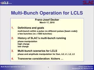
Multi-Bunch Operation for LCLS. Franz-Josef Decker March 17, 2010 Definitions and goals multi-bunch within a pulse ( vs different pulses [beam code]) a few bunches ( vs >1000 bunches) 2. History of SLAC’s multi-bunch running phase manipulation high charge low charge

Multi-Bunch Operation for LCLS
E N D
Presentation Transcript
Multi-Bunch Operation for LCLS Franz-Josef Decker March 17, 2010 Definitions and goals multi-bunch within a pulse (vs different pulses [beam code]) a few bunches (vs >1000 bunches) 2. History of SLAC’s multi-bunch running phase manipulation high charge low charge Multi-bunch scenarios for LCLS phase and amplitude manipulation for Gun, L0, L1, L2, L3 4. Transverse consideration: kickers …
Definitions and Goals • Multi-bunch: • few (2, 3, …) to many bunches (1400) within a pulse • SLC: 3 bunches, 60 ns apart • E-158: >1000 bunches every RF period, 6.5E11 particles (>100 nC) [100pC/bunch] • E-155: >1400 bunches, 2.9E9 particles (effectively zero) (<500 pC) • Different pulses on different beam codes • e.g.: 60 Hz here and 60 Hz there separated by pulsed magnets, quads, … • or: 59.5 Hz to experiment and 0.5 Hz to BYKICK dump • Goals for LCLS (-I and/or -II): • Mainly a few bunches up to 8 (420ns/60ns +1) for different undulators after separation by kicker magnets • Shorter separation possible if RF deflection is used (TCAV 4, 5, 6, …) • More bunches for one experiment (seeding, high power, target hit rate improved?) • Two bunches 105 mm apart + delay one (like sail-boat chicane for FACET)
RF Amplitude and Phase Change • SLC 1990: Energy spread for e-scav was not compensated: • RF phase was changed fast (30 ns) by 90 in compressor cavity to achieve about 6 integrated phase change in 60 ns:
RF Phase Manipulation • SLC 1990: 6.8 in 60 ns in NRTL LCLS 2009: 4.0 difference between over- and under-compression in L2 with SLED: 1/2 at input (1/3 at output) and 800ns fill time (600 ns NRTL): we need about 100 ns for 4 change
High power (600 kW) E-158 Beam • Energy of the different SLAC beams Conclusion: Transverse betatron lattices can be designed for beams with different energies like a factor of 2 in sector 4 or 1.8 in sector 10. The E-158 beam (blue, __) is at 45 (48) GeV at the end of the linac (3000 m) and has the highest energy along the linac. The scavenger beam (magenta, --) ends at 25.5 GeV, the PEPII beams for filling HER (red, -.) and LER (green, --) have an end-energy of 9.0 and 3.11 GeV.
Synchrotron Light on Gated Camera (60 ns) <6.5E11 particles E = 5 m 16%
Start of Pulse like Electron in BPM, Tail like Positron • Charge jitter caused energy jitter • Linac phase offset reduced energy jitter
Transverse jitter of beam tail Transverse (dispersive) jitter at end of pulse could be reduced from 300 m (shown) to 25 m rms by launching oscillations early in the linac Jittery setup Jitter of tail reduced, but “bowed” trajectory?
RF Tricks for Low Current (E-155) • Instead of one 180 switch PSK to make a SLED RF pulse use three, or five: • RF energy gain RF SLED pulse with notch
Double Notch in SLED Pulse • 0.5% energy variation 0.1%
Multi-Bunch Scenarios for LCLS • Five different longitudinal regions for LCLS (same parameter): • RF-Gun: effectively standing wave:(lower RF ampl. to keep peak, more power) • L0: traveling wave section no SLED (keep RF flat at low charge) • L1: traveling wave section with SLED (we have Ampl/Ph control for E and chirp) • L2: traveling wave section with old SLED (needs Ampl/Ph control, PSK for few bunches) • L3: traveling wave section with old SLED (needs Ampl control, PSK mostly o.k) • TCAV3 is an indication what is possible with EPICS RF system: L1S TCAV3 PSK A/P change 180 to compensate temperature, [300 ns gives 90, TCAV3 separates multi bunches] 100=1000ns
Energy Change after BC2 • If different energies are desired: L3 can give E = -5 GeV in 350 ns. (needs big notch for all SBSTs)
Transverse Effects • We saw mismatches with up to twice in beam size (Li01: 30% energy difference), so local compensation will be necessary for LCLS at least before BC2. • Separating the bunches to different beam lines (stability?) a) By kickers and septum/Lambertson magnets b) RF separators (TCAV) • Fast quadrupoles (kicker type) might not be necessary (Lattice for 2 * E is o.k.) • …
Diagnostics and Controls • BPM at 140 MHz: 2856/140 = 20.4 times 5 give 102 buckets or 35.7 ns, at this bunch delay the BPMs will see the sum of two bunches, at about 400 ns EPICS might be able to separate two signals. • BLM ? • Wires: 60 ns gate was used during SLC • Screens and cameras: 60 ns gated camera (maybe faster these days) • Feedbacks • Laser “stacks” now already two pulse, just delay one. More ideas: “just” ask Bill White • …
Summary • Multi bunch operation is possible with the SLAC Linac even for LCLS • Rule of thumb: RF can change: 10% in 80 ns (Tf= 800ns), with SLED half • Energy difference of up to 30% have been equalized to 0.1 % historically. • Transverse: One lattice can accommodate different energies • Kickers and multiple undulators are necessary for additional beam lines • Two bunches 105 mm apart and delay the first one in chicane eliminates timing jitter difference from two linacs