Download
1 / 77
1.24k likes | 2.2k Vues
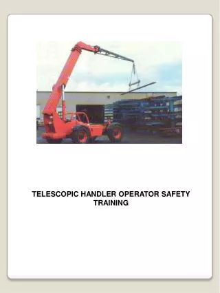
TELESCOPIC HANDLER OPERATOR SAFETY TRAINING. VARIIABLE REACH TELESCOPIIC HANDLER. OBJECTIVE: This training program is focused on this type of telescopic handler. IMPORTANCE OF TELESCOPIC HANDLER OPERATOR SAFETY TRAINING. What causes a telescopic handler to tip over?

E N D
VARIIABLE REACH TELESCOPIIC HANDLER OBJECTIVE: This training program is focused on this type of telescopic handler.
IMPORTANCE OF TELESCOPIC HANDLER OPERATOR SAFETY TRAINING What causes a telescopic handler to tip over? • The most common causes of tip over is going around a corner too fast without a load. • Turning with the forks above travel height, loaded or unloaded. • Handling a load that is too heavy for the telescopic handler does not cause as many tipovers as one might think. Why? Because when engaging the load, the telescopic handler “gets light” and we learn to keep such a load close to the ground. What are the most common reasons for being struck by a telescopic handler? • Driving with the load obstructing your vision. • Turning and not watching the rear end swing of the telescopic handler. • Backing up. For actual examples of telescopic handler accidents, go to: http://www.osha.gov/cgi-bin/inv/inv1sr?query= Industrial+Truck&querytp=KEYW Refer to quiz on page 2 of the student manual. Take turns answering the questions.
WHAT IS A PROFESSIIONAL? • You've carefully thought out all the angles. • You've done it a thousand times. • It comes naturally to you • You know what you're doing, its what you've been trained to do your whole life. • Nothing could possibly go wrong. PURPOSE: To instill in the student the importance of being a professional. This slide and the next are meant to be humorous. They illustrate the suddenness of accidents even to the most experienced professional. It is human nature to think that “it will never happen to me.” This can be dangerous in the long run.
Think Again Comment: “Accidents that cause injuries and death come suddenly and everyone is left scratching there heads and wondering what went wrong. Usually it is because they have been cutting safety corners for years and the “odds” finally caught up to them. After the accident it becomes evident that they weren’t being as safe as they thought they were. “How safe are we being?”
Captain E. J. Smith -- 1907 “When anyone asks me how I can best describe my experience of nearly forty years at sea, I merely say uneventful…. (I)n all my experience I have never been in any accident of any sort worth speaking about. I have seen but one vessel in distress in all my years at sea… I never saw a wreck and never have been wrecked, nor was I ever in any predicament that threatened to end in disaster of any sort.” Captain Smith became the captain of the Titanic in 1912 • • Here was a person that was a professional in every sense of the word but because of some mistakes on his last voyage his name and ship will always be infamous. • What were some of the mistakes that caused the disaster? • - Icebergs that far south were uncommon for that time of year. • - Desire to set a record for crossing the Atlantic Ocean. • - False sense of security that the Titanic was “unsinkable.” • - Not enough life rafts.
WHAT IS A PROFESIONAL? • Uses Safety Equipment • Desire to Learn • Skilled, Works to Improve • Controls Vehicle • Team Player • • Responsible • • On Time • • Rested, Alert • Physically Prepared • • Knowledgeable • • Wears Protective Clothing • • Gets Along with Others
TELESCOPIC HANDLER VS. AUTOMOBILES TELESCOPIC HANDLER AUTOMOBILES • Not for personal use • Weighs more than 5,000 lbs • Rear wheel steering • Training required • Operates on various surfaces • For personal use • Weighs less than 5,000 lbs • Front wheel steering • Training required • Operates on paved roads • Telescopic handlers should never carry passengers. • Telescopic handlers are heavy. They are easily 2 or 3 times heavier than a automobile. • The most significant difference is that a telescopic handler has rear wheel steering. The steering wheels can pivot almost 180 degrees. • Depending on the type of tires and chassis design, the telescopic handler can operate on different surfaces.
OPERATOR’’S MANUAL Operator’s Manual TH-742c TH-752c Acme Telescopic Handlers PURPOSE: Operator and Maintenance Manual is required to be on-board for each lift. • The operator is required to read and understand the Operator and Maintenance Manual prior to making a lift. • The manual is to remain on the telescopic handler. • Use the Operator and Maintenance Manual for the daily/shift inspections.
SIGNAL WORDS DANGER WARNING CAUTION Indicates imminently hazardous situation. If not avoided will result in death or serious injury. Indicates potentially hazardous situation. If not avoided could result in death or serious injury. Indicates potentially hazardous situation. If not avoided may result in minor or moderate injury. • All telescopic handlers will display these words along with a message about a potential injury situation. • Familiarize yourself where the different warnings are on the telescopic handler you are operating, • Familiarize yourself with situations that can cause an accident and how to avoid it.
SAFETY DECALS Safety Decals Must Be Legible And Kept Intact As Provided By The Manufacturer. Illegible Labels Need To Be Replaced. • All safety decals on the telescopic handlers must be present as intended by the manufacturer and must be legible. • 2. Any decal that is not legible must be replaced. • 3. Do not disregard the importance of these labels!
TELESCOPIC HANDLER TERMINOLOGY Tilt Cylinder Boom Extensions Sections Forks Main Boom Section Extension Cylinder Boom Lift Cylinder Boom Hinge Tires • Each of these components will be discussed in more detail with subsequent slides but briefly review each component. • 2. Telescopic handlers vary somewhat from manufacturer to manufacturer. If the telescopic handlers which your operating are somewhat different than these, please review the operator’s manual
PRE—OPERATIION INSPECTIION Visual Inspection • Overall Condition • Frame • Tires • Forks • Overhead Guard • Engine Compartment • Electrical Equipment • Control Labels & Markings • Operator’s Compartment The operator is responsible for conducting a pre-operation inspection at the beginning of each day or at the beginning of each shift. 2. There are a significant number of accidents which occur as a result of faulty equipment which would have been identified in the pre-operation inspection had it been performed.
PRE--OPERATION INSPECTION Damaged Overhead Guard CHASSIS Cracked Welds Loose Fasteners Leaking Fluids Cab Condition 1. Damaged overhead guards should be repaired. Damaged guards will not adequately provide the protection necessary from falling objects. 2. Inspect the suspension system for loose bolts. 3. Cleanliness of the cab is important. Grease and mud should be removed to prevent slipping. 4. All gauges and controls along with their labels need to be clean and legible. 5. Check for leaking fluids such as fuel, coolant, hydraulic fluid and etc. 6. Check structural welds for cracks. 7. Check the engine compartment for cleanliness.
PRE-OPERATION INSPECTION CHECKING FOR TIGHTNESS - Note The Accumulation Of Dirt And/or Paint Cracks In Paint Or Dirt Build-up Often Is Caused By Loose Bolts. CRACKED WELDS - TIRES AND RIMS -
PRE-OPERATION INSPECTION SWAY CONTROL LATERAL LEVELING - BOOM & COMPONENTS - FORK SECTION - Damaged Backrest Leaking Fluids
PRE-OPERATION INSPECTION Operational Inspection - • Seat Belt • Horn • Warning Devices • Gauges • Hydraulic System & Controls • Steering Mechanism • Parking Brake • Frame Sway Control • Service Brakes 1. Seat belts, if provided, need to be functioning properly. 2. Warning devices, including horns, lights and other devices must be operational. 3. All gauges should be checked for normal operations. 4. All the hydraulic functions need to be checked. The boom should be fully extended and retracted to ensure it operates smoothly. 5. Verify all of the steering functions are working properly. 6. Test the parking brake and the service brake to make sure they are functioning properly. 7. Test the sway controls. 8. Any control that functions erratically or is slow to respond needs to be repaired.
COMPLETION OF INSPECTIION • Report All Defects To Appropriate Individuals • Never Operate A Telescopic Handler In Need Of Repair • Only Authorized & Trained Personnel Make Repairs • The law states that a telescopic handler will not be operated which is not safe. • - Management is responsible for seeing that unsafe equipment is not used.
TELESCOPIC HANDLER STABILITY & CAPACITY
LOAD’S CENTER OF GRAVITY A point in the load around which all weight is evenly distributed • The point in the load around which all weight is evenly distributed, even if the load is irregularly shaped. RATED CAPACIITY • The manufacturer rates the capacity of the telescopic handler for a a specific weight located at a specific point on the forks. • If the load’s center of gravity varies from this specific “load center” then the capacity of the telescopic handler changes.
TELESCOPIIC HANDLER STABIILIITY Weight Behind The Front Axle Offsets The Weight In Front Of The Axle The front wheels are the pivot point of balance in the fore and aft directions. The machine’s center of gravity (CG) will be somewhere in the vicinity of the engine. The weight of the machine behind the front axle times the distance from the front axle to the machine’s center of gravity produces the off setting torque. The weight of the boom, forks, and the load ahead of the front axle times the distance from the front axle to the load produces a tipping torque. The off setting torque must always be greater than the tipping torque. The off setting torque is basically fixed and remains constant. The tipping torque can be increased by increasing the load weight or extending the boom out or both. When the load is lifted, a combined center of gravity is produced and will always be on a straight line between the load’s CG and the machine’s CG.
CHANGING STABILITY Combined CG is always on the line between load & machine CGs As the load moves farther from the pivot point the combined CG moves forward. The combined CG will move forward as the load is moved forward by extending the boom. If the combined CG moves past the from wheels, the machine will tip forward. 1. As the load is raised, the combined CG will move upward also. Note that the combined CG will move backwards slight when the boom is raised but not extended. A high combined CG has its greatest impact on stability when the machine is moving.
CHANGING STABILITY Extending the boom with a heavy load will result in the machine tipping forward if the tipping torque becomes greater than the offsetting torque. 2. Operators need to be cautioned that a load which is stable close to the machine will become less stable as the boom is extended. The weight of the load along with the load chart needs to be taken into consideration before extending a load.
LIFT CAPACITY CHART 1. Review each part of the chart. When a letter becomes visible on the boom as it is extended, the lift capacity then is reduced to the next lower capacity, regardless of how little the boom is extended beyond the visibility of the letter. The lift capacity decrease as an extend boom is lowered. And, the reason is that the tipping torque increases due to the horizontal distance between the load’s CG and the front axles is increasing. The lifting capacity shown is for the machine being perfectly level, on a solid surface, and no wind.
LIFT CAPACITY CHART The lift capacity chart must be legible and visible to the operator. The chart shows the machines lifting capacity at different boom lengths and boom angles. Review the diagram and make sure that you understand each part of the chart.
LIFT CAPACITY CHART This applies only to machines which have stabilizers. Note how the lift capacity increases when the stabilizers are properly deployed. The operator needs to make sure he is referencing the correct chart when determining his load limits.
EFFECTS OF STABILIZERS Using the stabilizers increases the machine’s lifting capacity. When making a maximum lift with the stabilizers down, the operator must make sure the load is retracted sufficiently before raising the stabilizers. If not, the machine could tip forward.
ATTACHMENTS TO THE TELESCOPIC HANDLER The capacity of the telescopic handler is affected any time an attachment is added to the machine. The attachment will: • Add weight to the front of the machine causing it to be partially loaded • The additional weight may extend the load center If you want to add an attachment to the telescopic handler after you receive it from the manufacturer, you must: • Have written approval from the manufacturer • Have a new capacity plate installed on the telescopic handler indicating the new capacity when using the attachment. The plate is only available from the manufacturer. • Attachments alter the telescopic handler’s load capacity and stability. • The warning plate needs to be changed to reflect the telescopic handler’s current configuration.
ATTACHMENTS TO THE TELESCOPIC HANDLER
DYNAMIC AND STATIC CONDITIONS • The telescopic handler’s balance is affected by both static and dynamic conditions. • Static conditions are those which affect the telescopic handler • when it is not moving. • Dynamic conditions are created when the telescopic handler • is moving. Static conditions include: • Load size • Load shape • Position of load on forks • Lift height • Amount of tilt • Tire pressure Dynamic conditions include: • Acceleration • Speed • Braking • Ramps and slopes • Raising load • Lowering load • Static Conditions are those that remain constant regardless of motion. • Dynamic Conditions are created as the telescopic handler moves and as the load is moved around. - Acceleration and breaking can cause additional load forces to be placed on the telescopic handler. Emphasis how breaking can cause the telescopic handler to tip forward. This affect is increased as the load is raised. - Uneven surfaces can also cause the telescopic handler to become unstable - again the degree of instability is primarily affected by the height of the load.
DYNAMIC FORCES & STABILITY The law of motions states basically that an object at rest wants to remain at rest and an object in motion wants to remain in motions unless acted upon by an external force. These two laws impact the stability of the machine when moving a load. 3. When a telescopic handler that is transporting a load stops, the load wants to continue moving. The additional force created by this movement will want to tip the machine forward. 4. The pivot point for this tipping motion is the front wheels and the distance from the ground to the load center is the effective lever arm. The forward motion of the load times the effective lever arm will produce a dynamic tipping torque. This dynamic tipping torque is added to the static tipping torque which the off setting torque must oppose or the machine will tip over. 5. The amount of forward force is dependent on how fast the machine is stopped. Braking fast will create greater tipping torque while slowly coming to a stop will produce a small tipping torque.
DYNAMIC FORCES & STABILITY 1. The higher the load is elevated, the greater the effective lever arm and therefore the greater the dynamic tipping torque will be. 2. The higher the load is carried when transporting it, the greater the risk for a tip over.
DYNAMIC FORCES & STABILITY Moving the machine with the load low has minimal effect on stability. 1. Note how small the effective lever arm is when the load is carried low. 2. The dynamic tipping torque for this situation is small and thus the machine is much less likely to tip over when braked.
DYNAMIC FORCES & STABILITY 1. The machine’s lateral stability can be affected by dynamic forces created when taking a turn. 2. Making a turn with the load raised high allows the centrifugal force to create a greater dynamic tipping torque than if the load is low. 3. This problem is compounded when the machine is making an up hill turn.
LATERAL STABILITY 1. Lateral stability is the stability of machine from side to side. 2. When the load is carried low to the level ground, the combined CG will be on center line. 3. This is the most stable positions for traveling with the load.
LATERAL STABILITY When the load is raised on level ground and no wind is present, the combined CG will remain on the machine’s center line. 2. This is only true when the machine is level.
LATERAL STABILITY 1. Note how the combined CG moves toward the down slope wheels which become the pivoting point. 2. If the slope became steep enough, the combine CG will move past the wheels and the machine will roll over.
LATERAL STABILITY 1. The combined CG moves upward as the load is raised. Because the machine is on a slope, the CG moves toward the direction of the pivot point wheels more rapidly and can result in a tip over. 2. For the same slope, the elevated load is more likely to cause a tip over than a load in the lowered position.
LATERAL STABILITY 1. Leveling the machine with the sway control will move the combined CG back toward the machines center line. 2. The machine’s lateral stability is restored.
LIFTING SUSPENDED LOADS When placing a crane arm on the telescopic handler for lifting suspended load, the manufacturer needs to be consulted to determine the new lifting capacities. 2. Traveling with suspended loads can cause additional dynamic forces which can result is a tip over. 3. Care must be used to prevent the load from striking the boom. This could result in the boom collapsing. 4. A lift capacity chart must be on the machine when such lifts are made. 5. Crane arms must be engineered with an established capacity identified.
SOIL BEARING STRENGTH & STABILITY 1. As the load is extended forward, the combined CG moves forward transferring more weight to the front wheel. 2. The stability of the machine can change dramatically if the pressure on the soil by the tires is greater than the soil strength. 3. Exceeding the soil strength will result in the tires sinking which could cause the machine to tip forward or over to the side.
SOIL BEARING STRENGTH & STABILITY 1. When the boom is extended, the pressure on the soil under the front wheels increases.
SOIL BEARING STRENGTH & STABILITY 1. This chart shows the soil strength of various types of soils. 2. The purpose of this chart is to show how soil strength can change. 3. Typically, the soil strengths around construction sites is poor because it has been disturbed.
SAFE OPERATING GUIDELINES OPERATOR QUALIFICATIONS • Only trained and authorized operators shall be permitted to operate a telescopic handler. • Operators of telescopic handlers shall be qualified as to visual, auditory, physical, and Mental ability.
OPERATOR TRAINING • The user shall ensure that operators understand that safe operation is the operators responsibility. • An effective operator training program should center around user’s company policy, operating conditions, and telescopic handlers. • The training should be presented completely to all new operators and not be condensed for those claiming previous experience.
SAFE OPERATING GUIDELINES • Safe operation is the responsibility of the operator. • The operator shall develop safe working habits. • He shall be familiar with all controls and instruments. • He shall be familiar with the Operators Manual.
SAFE OPERATING GUIDELINES • • Before beginning to operate telescopic handler: • fasten seat belt, if so equipped; • b) place directional controls in neutral; • c) disengage clutch on manual • transmission, or apply brake on power • shift or automatic; • d) start engine.
SAFE OPERATING GUIDELINES • Do not start or operate telescopic handler, any of its functions, or attachments from any place other than the designated operators position. • Keep hands and feet inside the compartment. • Never put any part of the body into the mast structure or within the reach mechanism or other attachments. • Check clearance under electrical wires, bridges, etc.
SAFE OPERATING GUIDELINES • Understand limitations of telescopic handler so as not to cause injury to personnel. • Do not drive telescopic handler up to anyone standing in front of an object. • Exercise care at cross-aisles, doorways, and other locations where pedestrians may step into the path of travel.
SAFE OPERATING GUIDELINES • Do not allow anyone to stand or pass under the elevated portion of the telescopic handler, whether empty or not. • Do not permit passengers to ride on the telescopic handler unless a safe place has been provided by the manufacturer. • Maintain a safe distance from the edge of ramps, platforms, and other similar working surfaces. • Do not block access to fire aisles, stairways, and fire equipment.