13 SEER Ductless Mini Splits
500 likes | 655 Vues
13 SEER Ductless Mini Splits. Product, Applications, Installation & Troubleshooting 2009. QUI-QSMSPAL-002. Basic Mini Split Applications. Computer or Data Rooms Commercial Spaces e.g. Offices, Shops, Churches and Eating/Drinking establishments Residential

13 SEER Ductless Mini Splits
E N D
Presentation Transcript
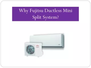
13 SEER Ductless Mini Splits Product, Applications, Installation & Troubleshooting 2009 QUI-QSMSPAL-002
Basic Mini Split Applications • Computer or Data Rooms • Commercial Spaces e.g. Offices, Shops, Churches and Eating/Drinking establishments • Residential • All 3 have different rules of thumb when it comes to sizing and also the accessories needed for proper operation, but the general rule of SIZE THE UNIT TO THE ROOM must be used. For specific applications always use a Manual J
Computer/Data Rooms • Basic Rule of thumb Sizing : • 250 to 275 sqft per 12,000 Btu/h • 24/7 operation 365 Days a year • MUST install an ICM low ambient controller and a crankcase heater • Must keep Air Filters clean as the unit could freeze up if the filters are not cleaned monthly
Commercial Installations • Basic Rule of Thumb Sizing : • 400 to 450 sqft per 12,000 Btu/h • May be in cooling operation 365 Days a year • If this is the case we MUST install an ICM low ambient controller and a crankcase heater • Make sure line set lengths are kept below the maximum line set length stated
Residential Installations • Basic Rule of Thumb Sizing : 550 to 600 sqft per 12,000 Btu/h • Keep the Indoor unit a minimum of 4ft from the floor with no obstacles within 15ft in front of the unit for the 9/12k and 25ft for the 18/24k units • Master Bedrooms to save energy or have a different temperature • FROG’s or Bonus Rooms where ductwork can’t reach
Requirements before Installation • Correctly sized Indoor/Outdoor Units, they must be a matched pair • Correctly sized breaker/disconnect • Line set, with both pipes insulated • Electrical Interconnect wire – must be a minimum of 14 AWG • 5/16” Gauge adaptor for R410A gauges • Small Electrical screwdriver for terminal connections • Low Ambient Control and crankcase heater if the application requires cooling below 65 DegF • Reading the Installation and Operation manual
Locating Indoor Unit • Install Indoor unit so it can deliver air into the room and return it to the unit, no obstacles to airflow within 10ft of the unit • Must be a minimum of 5ft from the floor • DO NOT THINK OF THIS AS A PTAC • If installing multiple units allow a minimum of 15ft on center between Indoor units on the same wall
Indoor Unit Installation Remove the plate from the rear of the unit, it is held on by a Philips head screw Mount the plate on the wall, make sure the plate is level, bend the mounting tabs out slightly to ease unit mounting Using the Templates provide, locate and drill a Ø3” hole at an angle of 5° downward towards the outside of the building to allow the line set and condensate hose to reach the outside
Indoor Unit Installation Rotate the pipes and tape the condensate hose to the pipe – hose must be at the bottom – I like to also add the interconnect wiring at this point to save time and effort trying to thread the wire through the wall hole with the unit in place If a Romex connection for electrical is required to satisfy local codes a ½” connector is provided on the rear of the unit On Heat Pump units the condenser coil sensor must be connected to the Outdoor unit so run that along with the refrigerant piping and interconnect wiring
With Indoor unit mounted • The refrigerant pipes can now be carefully bent to the required angle – Suction line has corrugations to prevent kinking • Condensate hose can be run to outside or to building drain – always use rigid piping Connection from unit fits a ¾” OD, 5/8” ID Vinyl PVC hose perfectly
Install the Outdoor unit • Ensure unit is not exposed to high winds – possible wind baffle required • Raise Heat Pump units at least 4” from ground or pad to help draining during defrost • Outdoor unit provides power for Indoor unit so a local disconnect will be required
Refrigerant Line Sets Unit Sizes Max Length & lift QSCE/HE09 ¼” & ½” 50ft inc 20ft lift QSCE/HE12 ¼” & ½” 50ft inc 20ft lift QSCE/HE18 3/8” & 5/8” 50ft inc 20ft lift QSCE/HE24 3/8” & 5/8” 50ft inc 20ft lift Lengths include all fittings and bends etc DO NOT UPSIZE LINE SETS BOTH LINES MUST BE INSULATED NO FILTER DRIERS OR SIGHT GLASSES
Line Set Connections • Keep both ends of the line set sealed until it is time to connect • Flare connections at both units – we do not recommend brazing • Adding a little vacuum pump oil on flare nut threads helps get them started • Always use 2 wrenches to prevent kinking • Currently units are not supplied with flare nuts unless our line sets are used
Leak Test & Evacuation • Gauge connections on the Schrader's are 5/16” not ¼” to prevent confusion – Adaptors Yellow Jacket # 19173 are required • Once line set is connected at both ends leak check with dry nitrogen • Do not let line set sit open to atmosphere place on vacuum ASAP • Vacuum down to a minimum of 200 microns to ensure all moisture is removed • Double evacuation, with a break using dry Nitrogen is recommended for full system cleanliness
Refrigerant Charging • Always open Suction valve first – uses a 6mm Hex wrench, then open “Liquid” valve with a 5mm Hex wrench • Doing this can prevent the Cap Tube, located behind the “liquid” line service valve becoming oil logged, putting the unit into a vacuum on initial start up
Refrigerant Charging Units are charged for line sets of 25ft as standard QSCE/HE 09/12 Add 0.2oz/ft over 25ft QSCE/HE 18/24 Add 0.5oz/ft over 25ft UNIT LINE SET RUN <25’ 30’ 35’ 40’ 45’ 50’ QSCE/HE 09/12 0 1.5 3.0 4.5 6.0 7.5 QSCE/HE 18/240 2.5 5.0 7.5 10.0 12.5 ADDITIONAL R410A MUST BE WEIGHED IN USING A DIGITAL SCALE
Electrical - General • Control Voltage is always Line Voltage • Use a minimum of 14AWG to connect Outdoor unit to Indoor unit • Up to 6 Interconnect wires are required depending on the unit model, 3 Power and 3 Control, don’t forget to connect the Heat Pump defrost sensor • Never install a local disconnect at the Indoor unit or any J boxes in between the Outdoor & Indoor
Electrical Stage I • Power the Outdoor unit from the local breaker & disconnect • QSCE/HE 091 115V 15A • QSCE/HE 121 115V 15A • QSCE/HE 181 208/230V 20A • QSCE/HE 241 208/230V 25A • Tip – To connect the whip liquid tight connection take the bottom plate off first and connect it off the unit
Electrical Stage II • Outdoor unit MUST provide power for the Indoor unit • Either L1 or L3 ON THE OUTDOOR UNIT MUST BE WIRED TO L1 or L3 ON THE INDOOR UNIT • Either N1 or L4 ON THE OUTDOOR UNIT MUST BE WIRED TO N1 or L4 ON THE INDOOR UNIT • Polarity is EXTREMELY important with these units
Electrical Stage III • If unit is a Heat Pump don’t forget to connect the Defrost Sensor between the Indoor and Outdoor units (Extend with 18AWG if necessary, 25ft of wire is provided) • To locate connector inside the Outdoor unit will require removal of top panel • Unit will not operate in Heat Pump mode without this wire being connected – will show an error code – 7 Blinks
Installing Low Ambient controls • Low Ambient Control ICM326H • Crankcase Heater (Mars or Raychem) – wire this directly to the line voltage connections – 115V for QSCE/HE 09/12 and 208/230V for QSCE/HE 18/24
Installing the ICM 326H • Fan Motor is Ball Bearing • Temperature Probe should be mounted on a 100 DegF return bend on the condenser coil – this is typically 3 to 4 return bends down from the top of the condenser coil • Set cut out speed to middle of setting • Wiring – See the diagrams in the Quietside 107 • Line voltage from common tap to the motor to the Line 1 connector • Cut speed tap to the motor and run it through the ICM – Line 2 and Motor 2 • Set Up controller • Cut Out Speed – halfway into the ball bearing range • Hard Start – halfway into the ball bearing range
Data Room or do you still want Cooling below 32 DegF? • Wind Baffles • Make your own, using our specifications and dimensions • Install both on Front and Rear of condensing unit for those windy locations and extreme cold • Allows Cooling operation down to 0 DegF
Unit Start up • On initial power up of the unit, it will immediately start the Outdoor unit in the cooling mode Do not power the system until it is ready to be started • Use the remote control to put the unit into the required modes to test operation • In Heat Pump mode the Indoor fan will run for 12 seconds to sense air temperature and then stop until Indoor coil temperature reaches 98 DegF • 3 Minute Anti Short Cycle Timer built into the system, along with Auto restart after a power failure
Control Modes • Auto, Cool, Heat, Dry and Fan Modes • Unit has a 24hr clock for the timer function, this allows a SINGLE event (On/Off) to be programmed for a certain time, for repeating events unit must be reprogrammed – Note 12pm/am actually is 0 hour • 3 minute time delay between compressor starts unless the unit is shut down, then the unit will start immediately
Control Modes • Auto, Cool, Heat, Dry and Fan Modes • Auto – Basic set temp is 74 DegF, unit chooses mode and fan speed based on room temp • Cool – User set temp & fan speed, unit controls to -2 DegF from room temp • Heat - User set temp & fan speed, unit controls to + 2 DegF on room temp • Dry – User set temp, fan speed unit set to low • Fan – Fan operation only, user sets fan speed, no cooling or heating function
Std Operating Pressures/Temps • Cooling Mode (80/67 & 95°F) • QSCE/QSHE 09/12/18/24 Suction Psig : 115psig = 37°F Superheat : 8°F Indoor Temp Split 30-35°F • Heating Mode (70°F & 47°F) • QSCE/QSHE 09/12/18/24 Liquid Psig : 400psig = 117°F Temp Split Indoor : 30°F
Troubleshooting • Indoor unit has 5 Troubleshooting codes and 2 • operational codes • Blinking once : Initial start up in H/P mode • Blinking Twice : Room Temp Sensor failure • Blinking 3 times : Coil Temp Sensor failure • Blinking 4 times : Outdoor unit error • Blinking 5 times : Freeze protection • Blinking 7 times : Outdoor sensor failure/not connected (Heat Pump only) • Constant Blinking : Defrosting
Fault codes in detail • Initial start up in H/P mode – Indoor coil temperature has not reached 98 DegF when first started in the Heat Pump mode • Room Temp Sensor failure – Unit cannot read the resistance of the Room temperature sensor • Check the sensor connections and resistance • 60 DegF = 7,000Ω • 70 DegF = 5,700Ω • 80 DegF = 4,700Ω
Fault codes in detail • Indoor Coil Temp Sensor failure – Unit cannot read the resistance of the Room temperature sensor • Check the sensor connections and resistance • 30 DegF = 14,000Ω • 40 DegF = 11,000Ω • 50 DegF = 8,800Ω • Outdoor unit error – After the compressor has been running for a period of 5 minutes, if the Indoor coil temperature does not show the expected change in temperature, in cooling the temp should be below 77 DegF, in Heating coil temp should be above 86 DegF • Check compressor operation, refrigerant flow
Fault codes in detail • Freeze Protection – If the Indoor coil temperature is below 32 DegF after 10 minutes of compressor operation or is below 5 DegF after 5 minutes of compressor operation the unit will shut down • Check refrigerant charge, filter condition, Indoor airflow • Defrost Sensor Error – Heat Pump units must have the Defrost sensor connected between the Outdoor and Indoor units, otherwise it will not operate in Heat Pump mode • Unit will run in Cooling mode but will immediately error out if switched into heating • Check the sensor resistance and connections between the units
Fault codes in detail • Defrost – Defrost operation is based on a combination of several factors • If the Compressor has been running for 45 minutes total, Outdoor coil temperature is below 23 DegF for at least 1 minute and the compressor has been on for 3 minutes continuously the unit will enter defrost • If the Unit has been in operation for 30 minutes before being turned into Heat Pump mode it will enter defrost • If the Outdoor coil temp is below 28 DegF when the unit is turned on in Heat Pump mode it will enter defrost • A defrost cycle will last a maximum of 8 minutes or the time taken for the Outdoor coil to reach a temperature of 59 DegF
Other Troubleshooting • Voltages can be measured from either L1, N1 or L3, L4 to 1, 2, and 3 to determine if compressor, Outdoor Fan and Reversing Valve are being called for • Check for the signal at both the Indoor and Outdoor units
Other Troubleshooting No Heat Pump Heating Check that the unit is actually in the Heat Pump Mode Sun = Heat Pump What looks like a Flame is actually a drip, putting the unit in de-humidification mode which is cooling with a low fan speed Check output for the 4 way valve energized for heating will default into the cooling mode, line voltage at #2 terminal, follow down to the solenoid coil
Troubleshooting during operation No PCB Output Check for line voltage at Power terminals Remove interconnecting wires, check for outputs in cooling in heating mode Check terminals, down to ground? Check for operation lights on the units Check fuse on PCB – 6.3A @ 250V, Radio Shack #270-1068 Check molex plug connections on PCB Check PCB receives signal from remote
Dual Zone Refrigerant Lines Unit Sizes Max Length & lift QSIHD09 ¼” & 3/8” 50ft inc 20ft lift QSIHD09 ¼” & 3/8” 50ft inc 20ft lift QSIHD12 ¼” & ½” 50ft inc 20ft lift QSIHD12 ¼” & ½” 50ft inc 20ft lift Lengths include all fittings and bends etc DO NOT UPSIZE LINE SETS BOTH LINES MUST BE INSULATED NO FILTER DRIERS OR SIGHT GLASSES
Dual Zone Connections • 18k unit has dual service valves • Unit A on top, Unit B below • EEV’s are before the service valves
Dual Zone Connections 24k • 24k system uses a manifold style connection with a single set of service valves • Unit A is top set, Unit B is the bottom set • EEV’s are after the service valves 24k
Leak Test & Evacuation • Gauge connections on the Schrader's are 5/16” not ¼” to prevent confusion – Adaptors Yellow Jacket # 19173 are required • Once line set is connected at both ends leak check with dry nitrogen • Do not let line set sit open to atmosphere place on vacuum ASAP • Vacuum down to a minimum of 200 microns to ensure all moisture is removed • Double evacuation, with a break using dry Nitrogen is recommended for full system cleanliness
Dual Zone Refrigerant Charging Units are charged for line sets of 25ft as standard QSIHD 09 Add 0.3oz/ft over 25ft QSIHD 12 Add 0.3oz/ft over 25ft UNIT LINE SET RUN <25’ 30’ 35’ 40’ 45’ 50’ QSIHD 09 0 1.5 3.0 4.5 6.0 7.5 QSIHD 12 0 1.5 3.0 4.5 6.0 7.5 ADDITIONAL R410A MUST BE WEIGHED IN USING A DIGITAL SCALE
Dual Zone Electrical • SINGLE wire low voltage communication signal between Indoor units and Outdoor units • Separation required to the high voltage power wiring • 14AWG Power wires, Communication wire can be minimum 16AWG • Do not ground Indoor units or shield communication wires
Maintenance QSCE & QSHE • Monthly : Large filters must be cleaned • 6 monthly : Check indoor fan blade for dust and debris build up, check condensate pan for any debris • Yearly : Clean coils – we recommend soapy water not a harsh acidic type, check both electrical and refrigerant connections for tightness and insulation on the pipes
Unit Warranty • 5 Years Compressor • 1 Year all other parts, including refrigeration system parts • 90 Days limited labor from date of start up • All warranties commence on date of installation • Warranty parts are shipped ground on receipt of a completed warranty claim form
Literature Support • Sales Brochures • Engineering Submittals • Installation and Operation Manuals • Quietside Basic Technical • Quietside 107 – Application and Troubleshooting • Quietside Basic Product and Application Power point presentation • Quietside advanced Technical Training for Distributors and Contractors
Support Contacts Sales Support Local Representation Quietside sales staff Regionalized Customer Support Technical Support East Coast 866 243 6498 Denis, Mike, Chris West Coast 888 699 6067 x 3 John, Stu, Kevin www.Quietside.com