Download
1 / 96
970 likes | 1.16k Vues
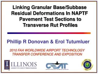
Linking Granular Base/ Subbase Residual Deformations In NAPTF Pavement Test Sections to Transverse Rut Profiles. Phillip R Donovan & Erol Tutumluer. 2010 FAA WORLDWIDE AIRPORT TECHNOLOGY TRANSFER CONFERENCE AND EXPOSITION. Acknowledgments. Dr. Phillip R Donovan, Major, US Air Force

E N D
Linking Granular Base/Subbase Residual Deformations In NAPTF Pavement Test Sections to Transverse Rut Profiles Phillip R Donovan & Erol Tutumluer 2010 FAA WORLDWIDE AIRPORT TECHNOLOGY TRANSFER CONFERENCE AND EXPOSITION
Acknowledgments • Dr. Phillip R Donovan, Major, US Air Force • FAA research funding provided for Center of Excellence for Airport Technology (CEAT) established at UIUC “Analysis of NAPTF Trafficking Dynamic Response Data for Pavement Deformation Behavior” • Dr. David Brill, FAA Tech Center • Dr. Gordon Hayhoe, FAA Tech Center
Introduction • The NAPTF CC1 tests indicated that applying a sequential offset load (wander) pattern to thinly surfaced asphalt pavements could reduce or even negate immediate surface deformations • The downward residual deformation caused by a pass of heavily loaded gear carriage was canceled by the upward residual deformation (heave) resulting from the pass of the same gear offset by wander (Hayhoe & Garg, 2002)
Stresses Beneath Moving Wheel (Brown & Chan 1996, Lekarp et al. 2000, Hornych et al. 2000, Kim & Tutumluer 2006)
Stresses Beneath Offset Moving Wheel sh > sv σ1 σ3 σ3 σ1 σ3 Wander Offset σ1 Offset wheel loads can potentially shift & rearrange unbound aggregate materials horizontally & increase damage to the system
NAPTF Wander Position & Direction W-E North Lane 2 1 South Lane E-W
Objective of Paper Use Multi-Depth Deflectometer (MDD) & transverse profile data from NAPTF CC1 tests to estimate P209/P154 base/subbase permanent deformation trends & accumulation rates due to traffic loading applied with wander
NAPTF – Test Measurements - MDDs 5 in. (127 mm) P401 Surface 5 in. (127 mm) P401 Surface 5 in. (127 mm) P401 Surface 5 in. (127 mm) P401 Surface 5 in. (127 mm) P401 Base 5 in. (127 mm) P401 Base 8 in. (203 mm) P209 Base 8 in. (203 mm) P209 Base 8 in. (203 mm) P209 Base 12 in. (305 mm) P154 Subbase 30 in. (762 mm) P209 Subbase 36 in. (914 mm) P154 Subbase 102 in. (2591 mm) Medium Strength Subgrade CBR – 8% 95 in. (2413 mm) Medium Strength Subgrade CBR – 8% 104 in. (2642 mm) Low Strength Subgrade CBR – 4% 95 in. (2413 mm) Low Strength Subgrade CBR – 4% MFC MFS LFS LFC MDD Sensor
Definition of Residual and Rebound 6-wheel dual-tridem (B777 type) gear Begin avg & Max Residual End avg Rebound Min
Transverse Surface Profiler (TSP) Permanent 28 passes NAPTF CC1 MFC Section 6-wheel gear 5,001 passes 10,202 passes 12,952 passes Max Coverage Location MDD Location
Wander Distribution 66 passes