Download
1 / 7
70 likes | 103 Vues
Investigation of dark artifacts in radiographic images from mobile x-ray units. Detailed analysis of causes including detector damage, incorrect correction map, and physical objects. Solutions and in-depth discussions on artifact sources and corrections.

E N D
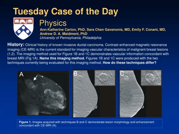
History: Radiolucent (dark) artifacts were noted by radiologists on images acquired using several mobile DR x-ray units. In addition, embedded accelerometers indicated the detectors may have been dropped. Tuesday Case of the Day • The likely cause of the artifact is: • Detector damage • Objects in the imaging path unrelated to the detector • Out-of-date correction map • Incorrectly obtained correction map Physics Authors: Laurence Parr, MS, DABR1 and Charles E. Willis, PhD, DABR2 1Department of Radiology, Naval Medical Center Portsmouth, VA 2U.T. M. D. Anderson Cancer Center, Houston, TX Normal window Narrow window Pediatric KUB 70 kVp 5 mAs Adult Chest 110 kVp 6 mAs Figure 2. Uniform exposure images showed numerous similarly sized bright and dark parallelogram-shaped defects. Figure 1. Examples of the artifact (red arrows) are representative of those seen on all images.
2.A second uniform exposure image acquired after rotating the detector 180º showed numerous increased (dark) and decreased (light) signal artifacts (Fig. 4). • 1. After recalibration, a uniform exposure image acquired without moving the detector showed no artifacts (Fig. 3). Findings: The detector was recalibrated according to the manufacturer’s directions. Handle Edge Handle Edge Figure 4: Uniform Exposure – rotated180º Figure 3: Uniform Exposure – calibration orientation
5. The decreased signal artifacts (light) did not correlate with the correction map. 4. The correction map image (Fig. 5) showed focal regions of increased correction values that correlated with the increased signal artifacts (dark) on the rotated image (Fig. 6). 6. Radial symmetry through the center of the 180º rotated image was noted between the dark and light artifacts (Fig. 6). Findings: (continued) Handle Edge Handle Edge Figure 6: Uniform Exposure – rotated180º Figure 5: Correction Map – rotated 180º
Diagnosis:B. Objects in the imaging path unrelated to the detector
Physical damage to the detector would have resulted in artifacts that maintained a fixed orientation with respect to the detector. Therefore, choice A. Detector damage is incorrect. Recalibration only corrected the problem so long as the detector orientation was maintained. Therefore, choice C. Out-of-date correction map is incorrect. Several small lead filings were found on thecollimator exit window of the x-ray generator. After the filings were removed and the detector was recalibrated, the artifacts no longer appeared in any detector orientation. Calibration produced a gain correction map that was appropriate for the conditions of exposure, as demonstrated by the initial disappearance of the artifacts. Therefore, choice D. Incorrectly obtained correction map is incorrect. Discussion: Reappearance of the artifacts after calibration when the detector was rotated indicates the source of the artifact is not fixed in position relative to the detector. If the source of the artifact had been fixed in position relative to the detector, recalibration of the gain map would compensate and the artifact would not reappear when the detector was rotated. This dark artifact is over-correction at the time of imaging in an area of the detector where low exposure existed at the time of calibration. Handle Edge This light artifact is an area of low exposure on the detector at the time of imaging where uniform exposure existed at the time of calibration. Figure 7: Light artifacts are focal spot images from the inverse pinhole effect. Dark artifacts are over-compensation in the gain correction map where focal spot images were present during calibration.
The artifacts have the typical “double-banana” shape of a focal spot image. A small amount of high Z material in the x-ray beam path, such as the Pb filings in the collimator exit window, can produce the image of the focal spot in the image receptor plane. This artifact was first reported in diagnostic radiology by Poznanski (1969). Discussion: The artifacts are, in fact, images of the focal spot of the x-ray generator, by means of the inverse pinhole effect. Figure 8: Slit camera image of the focal spot (Jones 2008). Figure 9: Xeroradiograph at 60 kVp and 40 mAs of an inverse pinhole array. The inverse pinholes are tungsten from 75 -300 micron in diameter arrayed in ten rows from left to right on a sheet of lucite (Cowart 1976). Note the distortion of the focal spot projection as lateral distance increases from the central ray of the x-ray beam.
References/Bibliography: Cowart, RW. An investigation of the inverse pinhole camera. Thesis. University of Texas Health Science Center at Houston. Graduate School of Biomedical Sciences. Houston, TX. June 1976. 111 pages. Jones, AK. Personal communication. 2008. Poznanski, AK. Focal spot artefacts on breast radiographs. Radiology 92: 644. 1969.