Download
1 / 8
80 likes | 181 Vues
Perform steady-state simulation verifying tower diameter for Qmax & ρv column hydraulics using AspenPlus. Analyze profiles, hydraulics, and run the simulation to generate results. Learn Controller Tuning techniques for improved system response.

E N D
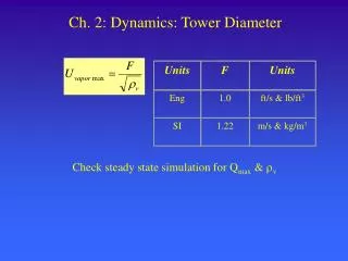
Units F Units Eng 1.0 ft/s & lb/ft3 SI 1.22 m/s & kg/m3 Ch. 2: Dynamics: Tower Diameter Check steady state simulation for Qmax & v
Column Hydraulics • Radfrac block • Report • include hydraulic parameters • Run simulation • Results • Radfrac Block • Profiles • Hydraulics tab • ASPENPLUS:
In-Class Exercise P = 2 bar sat’d liq 20 stages Feed = above stage 10 D = 11.8 kmol/hr RR = 1.5 Benzene 11.8 kmol/hr Toluene 11.8 kmol/hr
In-Class Exercise AspenPlus Tray sizing
Controller Type Kc (gain) I (reset time) F (filter) Flow 0.5 0.3 min 0.1 min Level (surge) 2 (reactor) 10 (others) See text Pressure 2 10 Chapter 3: Controller Tuning
Chapter 3: Controller Tuning • F, P, L - are simple controllers • Temperature & Composition • More difficult • Why ? • A: lags or deadtime • Simulators respond instantaneously • To make more realistic • Add lag time in control loop • Table 3.1 Typical values Rest of Chapter 3: Tuning techniques