Wastewater Treatment Plants
430 likes | 630 Vues
Wastewater Treatment Plants. WWTPs. Treatment Goal. Discharge of treated effluent will not harm aquatic communities or limit use downstream. Problems from improper treatment. Low DO level from excess BOD fish kills Sediment deposits in waterways Excess nutrients

Wastewater Treatment Plants
E N D
Presentation Transcript
Treatment Goal • Discharge of treated effluent will not harm aquatic communities or limit use downstream
Problems from improper treatment • Low DO level from excess BOD • fish kills • Sediment • deposits in waterways • Excess nutrients • Increased primary production • Toxic components remaining • ammonia, heavy metals, organics • Aesthetic problems
U.S. Federal Discharge Limits • 30 mg/L TSS • 30 mg/L BOD (much of this is in TSS) • pH 6-9 • Fecal coliform – 200 CFU/100 mL • Local standards typically are more stringent
Typical WWTP Processes • Primary treatment • Secondary treatment • Tertiary treatment (not as common) • Sludge management
Primary Treatment • Remove solid materials • large debris using screens • particulates using sedimentation • removes both mineral (grit) and organic (BOD) • some reduction of BOD • produces sludge that must be treated or managed • May provide flow equalization
Secondary Treatment • Biological conversion of dissolved and colloidal organic material • organic material (BOD) serves as food for microbes • microbes may be attached to surfaces or free-floating • excess microbial growth generates sludge that must be treated or managed
Tertiary Treatment • Advanced treatment processes for additional removal of suspended solids, BOD or nutrients • May include biological, chemical or physical processes that generally target specific components to be removed
Typical Municipal WWTP • screen • grit chamber • flow equalization • sedimentation • biological treatment (trickling filter or activated sludge) • sedimentation • disinfection
Primary Treatment • Screening • remove large objects (shoes, toys, branches) to keep from damaging pumps and pipes • typically use bar screens – vertical bars with narrow spacing to catch larger objects while allowing sediment and organic solids to pass • spacing from 0.5 cm to 4 cm • automatic rake or other mechanism to remove solids collected
Bar Screen Design • size to handle peak flow entering plant • required area determined by peak flow (Q) and approach velocity (v) • typical approach velocity • 0.6-1.2 m/s – mechanically cleaned • 0.3-0.7 m/s – manually cleaned • Area of screen: A = Q/v
Grit Chambers • Remove mineral solids while leaving organic solids in flow • Utilize higher density of mineral solids for rapid gravity settling • retention times usually short (1 to 5 min) • use sedimentation process described previously (Stoke’s Law)
Flow Equalization • Flow rate to treatment plant varies throughout the day • Treatment processes are more stable if flow rate is consistent • Equalization tanks store wastewater during peak flow periods and are drawn down during low flow to keep downstream flow about constant • Also helps smooth out fluctuations in BOD concentration to downstream processes
Equalization Tank Design • Need average flow rate and BOD concentration for each time interval throughout day • Generally pump wastewater from tank at average daily flow rate • Tank must be large enough to store all flow in excess of daily average • Mass balance on BOD determines changes in concentration in tank effluent
Primary Sedimentation • removes about 2/3 of organic solids and 1/3 of BOD • typically use clarifiers (settling tanks) with settled sludge scraped into hopper at bottom of tank • settling is typically floculant
Clarifier Design Parameters • surface overflow rate • volumetric flow rate into basin divided by the surface area of the basin: v = Q/A (Eq 1) (note this is the same eq introduced previously) • units of gal/ft2·d or m3/m2·d • typical values (based on settling lower density organic solids) • 600 – 1500 gal/ft2·d • 25 – 60 m3/m2·d • note that clarifier diameters generally are in 5 ftor 1 m increments, so round up
Clarifier Design Parameters • weir loading • rate at which water flows over side walls • volumetric flow rate (Q) divided by length of weir (L): W = Q/L (Eq 2) • units of gal/ft·d or m3/m·d • typical values (based on not creating turbulence near the exit) • 10,000 – 40,000 gal/ft·d • 125 – 500 m3/m·d
Clarifier Design Parameters • hydraulic retention time • average time water stays in clarifier • volume of clarifier divided by flow rate: θ = V/Q (Eq 3) • typical values: 1.5 – 2.5 h
Secondary Treatment • Reduce BOD by converting to settleable solids • usually aerobic biological growth used to convert BOD to microbial biomass • attached growth reactors • Trickling filters • Rotating biological contactors • suspended growth reactors • Activated sludge
Trickling Filters • Attached growth reactors containing rocks or synthetic medium to support growth • BOD removal given by (Eq 4) Li = effluent BOD5 (mg/L) L0 = influent BOD5 (mg/L) k = biodegradation rate constant [(ft·d)-1/2 or (m·d )-1/2] h = depth of filter bed (ft or m) A = volumetric flow rate Q = cross sectional area of filter tank
Activated Sludge • Suspended growth reactor • Requires aeration to provide oxygen • Most sludge (biomass) returned to reactor to consume BOD from incoming wastewater
Hydraulic Retention Time (Eq 6) θ =hydraulic retention time of wastewater (d) θc = hydraulic retention time of cells (d) Y =yield coefficient (mg cells/mg BODconsumed) S0 = influent BOD5 (mg/L) S = effluent BOD5 (mg/L) X =concentration of cells in reactor (mg/L) kd = decay (cell death) coefficient (d-1)
Possible Additional Components of Secondary Treatment • Biological nitrogen removal using nitrification to convert ammonia and ammonium to nitrate by aerobic treatment and then convert nitrate to N2 by anoxic treatment. • Biological or chemical phosphate removal
Sludge • Primary sludge • settled solids from primary treatment • solids content: 2 – 7 % solids • Secondary sludge • biomass generated by cell growth • flocculated solids not consumed by growth • trickling filter sludge: 1 – 5 % solids • activated sludge: 0.5 – 1.5 % solids
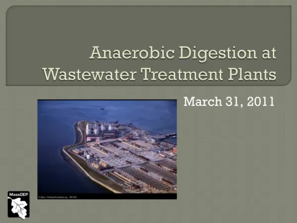
Sludge Management • Thickening • removes additional water from sludge • gravity thickening using additional clarifiers • dissolved air floatation to make solids float • Sludge stabilization • anaerobic digestion • aerobic digestion • lime stabilization • heat treatment
Sludge Management • Dewatering • drying beds • mechanical dewatering • Disposal • landfill • incinerate • land application