Download
1 / 27
270 likes | 421 Vues
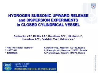
Hydrogen Subsonic Upward Release and Dispersion Experiments in Closed Cylindrical Vessel. Denisenko V.P. 1 , Kirillov I.A. 1 , Korobtsev S.V. 1 , Nikolaev I.I. 1 , Kuznetsov A.V. 2 , Feldstein V.A. 3 , Ustinov V.V. 3

E N D
Hydrogen Subsonic Upward Release and Dispersion Experiments in Closed Cylindrical Vessel Denisenko V.P.1, Kirillov I.A.1, Korobtsev S.V.1, Nikolaev I.I.1, Kuznetsov A.V.2, Feldstein V.A.3, Ustinov V.V.3 1 RRC ”Kurchatov Institute” 1, Kurchatov Sq., Moscow, 123182, Russia 2 NASTHOL 6, Shenogin str., Moscow, 123007, Russia 3 TsNIIMash 4, Pionerskaya, Korolev, 141070, Russia
Context: Russian R&D Programme “Codes an Systems for Hydrogen Safety” • grant of Russian Ministry of Science and Education • (2004-2006, cont. July 2007-2009): • for safety provisionof national hydrogen infrastructure • scientific basis for development of regulatory documents (codes/standards) • … • minimal number and allocation of sensors in confined areas • … • prototypes for subsequent commercialization of tools/components forintegrated safety systems • … • sensors • recombiners • inhibitors • …
Context: Problem: Allocation of sensors in confined areas • Technical questions: • How many ? What is a minimal number of gas detectors, which should be used in confined area, for safety provision ? • Where ?How should they be spatially allocated? • Land use problem: • absence of free space -> multiple-use of space -> confined sites undeground parking, 100+, ~5 kg H2 per auto
Context: Problem: Allocation of sensors in confined areas Practical reference case: according to current technical regulation of Ministry of Transport (VCN 01-89 Minavtotrans) Ministry of Emergency (NPB 105-03) gas*-fueled autotransport facilities and premises (parking, workshop, etc.) of category A should be equipped with gas-analyzers and alarm systems * - propane-buthane
Context: Problem - Allocation of sensors in confined areas Empirical approach: Qualitative guidelines “…Sensors should be positioned to detect any gas accumulation before it createsa serious hazard….” The selection and use offlammable gas detectors, HSE, TD05/035, 2004(p.8) “…Hydrogen detectors are typically placed above a likely leak point, where hydrogen may accumulate, and at the intake of ventilation ducts….” ISO-TR-15916 (p.5)
Context: Problem - Allocation of sensors in confined areas Empirical approach: Quantitative guidelines TU-gas-86. Requirements on arrangement of the indicators and gas-analysers RD BT 39-0147171-003. Requirements on arrangement of stationary gas-analysers in industrial facilities and on outdoor sites of oil and gas industry 1 sensor per 100 m2 Restricted application: for propane-buthane only
Context: Problem - Allocation of sensors in confined areas • Practical need: • Quantitative engineering guidelines (rational procedure) for selection of • a minimal number of sensors and • their spatial allocation within given confined space, which should be protected • Research prior art: • indirect relevance only • Extensive database for jets/plumes under open space conditions • For releases into confined space – fire detectors allocation studies
Scope of reported research work: • Overall goal • experimental characterization of the hydrogen sub-sonic* release and distribution inside of confined, unventilated space • baseline (reference) data for subsequent studies: • certain, accurate, repeatable, verifiable • Technical objectives • qualitative characterization of basic gas-dynamic patterns • quantitative measurements of ignitable envelope evolution * - “small foreseeable leakage” scenario
Approach: “Schiphol principle”: Mind your uncertainties ! • minimize experimental uncertainties ALAPR • identify anddocument uncertainties • balance ‘performance - uncertainty“ • propose affordable design of experiment
Experiment: Site layout Schematic drawing of protective concrete dome (R = 6 m, h = 6 m, H = 12 m) Ambient conditions (inside of dome): Air temperature 23ºC Air pressure 758 mm Hg Relative humidity 64 %
Experiment: Experimental chamber External (left) and internal (right) views of the experimental chamber
Experiment: Gauge net layout 2,22 м hydrogen source: circular tube (internal diameter - 0,012 m)
Experiment: Hydrogen sensors Thermal Conductivity Gauge TCG-3880 (is shown with open cap) by Xensor Integration (Netherlands) Acoustic sensor mounted at electronic card (for data processing and transmission) by RRC ”Kurchatov Institute”
Experiment: Gas supply and control gas mixture preparation device (GMPD): gas mixture composition up to 8 components steady gas flow rate [5*10-6 , 7*10-4 ] m3/s (from 20 to 2560 l/h).
Experiment: Procedure and Parameters Series 3 consecutive runs (inert gas purging between) with the same parameters Ambient conditions standard Hydrogen injection direction upward duration 10 min flowrate 0,46 l/sec Data acquisition Duration during injection and 15 min after its end Temperature sensors 24 (inside), 4 (outside) Hydrogen sensors 24 (inside) Pressure gauge 1 (inside), 1 (outside)
Experiment: First results: Hydrogen concentration time histories Time histories for the hydrogen concentrations (% vol.) for the 24 gauges (time duration 0 - 25 min)
Experiment: First results: Basic flow patterns: Pre-test simulations Evolution of Ignitable Hydrogen-Air Gas Mixture Cloud Three-phase evolution of ignitable gas mixture cloud Step 1 – upward propagation of emerging jet/plume, Step 2 – impinging of jet/plume with ceiling and outward expansion of cloud, Step 3 – downward expansion of cloud from ceiling to floor.
Experiment: First results: Basic flow patterns: Experimental results Evolution of Ignitable Hydrogen-Air Gas Mixture Cloud 10,05 min 1 min 15 min 5 min 25 min 10 min hydrogen concentration in % vol.
Experiment: First results: Experimental data for ignitable mixture front speed Averaged speed of envelope (2 % vol.) front propagation UNVENT#1 series (3 runs) envelope propagation speed Vert. (upward) - 0,33 m/sec, Horiz.(outward) - 0,055 m/sec. Definition of averaged speed using sensor 4 and sensor 21
Experiment: First results: Reproducibility of results Time histories for three different test runs (sensor 10)
Experiment: Synchronous behavior of sensors at symmetric points Symmetrical character of hydrogen flow in experimental vessel
Conclusions: • The experimental set-up for pre-normative studies of hydrogen release and dispersion inside of a medium-scale (4 m3), closed horizontal cylindrical vessel was prepared and adjusted. • The first precise measurements (3 test runs) of the time evolution of explosive hydrogen cloud after hydrogen injection under the well-controlled boundary/initial conditions have been carried out using spatially distributed 24 hydrogen sensors and 24 thermocouples. • Analysis of the simultaneous experimental records for the different spatial points permits to delineate the basic flow patterns of hydrogen subsonic release in closed vessel in contrast to hydrogen jet release in open environment. • The quantitative data were obtained for the averaged speeds of ignitable cloud envelop (50% fraction of the Lower Flammability Limit (LFL) – 2 vol.%) propagation in the vertical and horizontal directions. • It was proposed to use the uncertainty analysis of the experiments and simulations for benefit of the hydrogen safety studies
ACKNOWLEDGMENTS • This work was supported by • Russian Ministry of Science and Education and • EU HYPER project (partially).
Thanks for your attention ! Questions/comments:kirillov.igor@gmail.com
Context: Problem – Uncertainties in hydrogen safety studies SBEP-V1 Experiment vs Simulation (VNIIPO, 1988) (HySafe, 2005) Figure 1. (a) Shape of the experimental vessel Figure 8. Comparison between models (250 min after the end of release). From: www.hysafe.org/download/362/D23-01.doc
Context: Problem – Uncertainties in hydrogen safety studies SBEP-V1 Experimental uncertainty: during measurement phase (250 min), it was impossible to control the thermal boundary conditions


![[ID 204] Evaluation of ADREA-HF LES against Hydrogen release dispersion](https://cdn1.slideserve.com/3368999/id-204-evaluation-of-adrea-hf-les-against-hydrogen-release-dispersion-dt.jpg)