ELF
Dive into electromagnetic spectrum from Hz to GHz, complex waveforms, communication systems, modulation, wavelengths, and antenna technology. Discover how frequencies affect communication and radio systems. Learn about radio waves and wavelength calculations.

ELF
E N D
Presentation Transcript
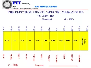
Wavelength Frequency THE ELECTROMAGNETIC SPECTRUM FROM 30 HZ TO 300 GHZ ( = 300/f) 10-1 m 10-2 m 10-3 m 10-4 m 105 m 104 m 102 m 106 m 103 m 107 m 10 m 1 m Millimeter waves ELF VLF LF MF HF VHF UHF SHF EHF VF 3 kHz 30 Hz 3 GHz 3 MHz 30 kHz 300 Hz 30 GHz 300 kHz 30 MHz 300 GHz 300 MHz (f = 300/)
HIGH FREQUENCIES • High Frequencies - 3 MHz to 30 MHz • Very High Frequencies - 30 MHz to 300 MHz • Ultra High Frequencies - 300 MHz to 3 GHz (1 GHz and above = microwaves) • Super High Frequencies - 3 GHz to 30 GHz • Extremely High Frequencies - 30 GHz to 300 GHz
THE ELECTROMAGNETIC SPECTRUM ABOVE 300 GHZ Wavelength 0.8 x 10⁻⁶ m 0.4 x 10⁻⁶ m 10-5 m 10-3 m 10-4 m Millimeter waves X-rays Ultraviolet Infrared Visible Gamma rays Cosmic rays 300 GHz
FREQUENCY AND WAVELENGTH • Cycle - One complete occurrence of a repeating wave (periodic signal) such as one positive and one negative alternation of a sine wave. • Frequency - the number of cycles of a signal that occur in one second. • Period- the time distance between two similar points on a periodic wave. • Wavelength - the distance traveled by an electromagnetic (radio) wave during one period.
COMPLEX WAVEFORMS • A complex waveform is any signal that is not a sine wave • a square wave • a triangle wave • a sawtooth wave • human voice • music • digital data • Any periodic signal that is not a pure sine wave can be considered to be built out • of the following components: • A dc component or “average”( which can be zero ) • A fundamental sine wave that has a frequency exactly the same as the • frequency of the signal • An infinite number of harmonics( a harmonic is a frequency that is exact • multiple of the fundamental frequency) • NOTE: in perfect square wave there are an infinite number of frequencies present. • we only need to analyze up to the 13th harmonic in order to get a decent • reproduction of a square wave.
Time domain (Oscilloscope) Pure of 1 kHz sine wave Frequency domain (Spectrum Analyzer) Picture of square wave
A 1 kHz square wave 500 milliV/Div 200 uSec/Div That shows on the oscilloscope A 1 kHz square wave 100 milliV/Div That shows on the spectrum analyzer
Receive Antenna Transmit Antenna Voltage Amplifier Voltage Amplifier Power Amplifier Power Amplifier Microphone • Electronic Communications is everywhere • Watch a TV broadcast or listen to the radio • Used a telephone • used remote control and more • Electronic Systems • A system can be defined as a group of components that work together to • complete a job or a task. • A subsystem is just a part of a system ; it helps to complete a task • A subsystem is often shown in a block diagram. • A SIMPLE RADIO SYSTEM • A microphone is a type of transducer. It converts the pressure variations in a sound • wave into electrical energy. • a transducer is any device that converts one form of energy into another. • The transmitting antenna converts the amplified information signal into a new form • of energy capable of traveling through space. This new energy is called • electromagnetic energy or radio wave. Electromagnetic energy consists of two fields • a voltage or electric field and a magnetic field. It travels through space at the speed • of light, which is about 3 x 10⁸ meters/second (m/s)
Transmitting Antenna Requirement • Radio transmitting antennas need to be at least one-quarter of a wavelength long. • audio frequencies are those we can hear. They are from 20 hz to 20000 hz • an audio frequency that is in the “middle” of our hearing range is 1000 hz or 1 khz. Let calculate the wavelength of a 1 khz electromagnetic wave • = v/f = ( 3 x 10⁸ m/s )/ 1 khz = 300 kilo meters • antenna need only be one-quarter of this distance or 75 kilo meters. • increase frequency always decreases wavelength • decreasing frequency always increases wavelength • Let try changing from 1 khz to 10 khz then = 30 kilo meters and length antenna = 30/4 = 7.5 km • if frequency f = 150MHZ then = 2 meters and L antenna = 2/4 = 0.5 m • MODULATION • 150 MHz signal may transmit just fine, but there’s one more problem. We can not hear a 150 MHz; it is too high in frequency. This is a solution; it’s called modulation. When we modulate a wave, we place a low-frequency information signal onto it. the low-frequency signal is just along for the ride. • it is in effect, “carried” on top of high frequency signal. The high frequency signal is therefore called carrier signal.
Many mobile FM radio units operate near 150 Mhz . At this frequency • Wavelength = v/f = 3 x 10⁸ m/s / 150 Mhz = 2 m • And Lmin = / 4 = 2m/4 = 0.5m = 19.7” • Frequencies above the range of hearing are called radio frequencies. Any frequencies above 20 kHz is considered a radio frequency. • EXAMPLE 1-1: • what is the wavelength of a 710 kHz AM broadcast signal? What is the minimum height of the antenna tower in feet if it is one-quarter of a wavelength long? • wavelength = v/f = 3 x 10⁸ / 710 kHz = 422.5m • / 4 = 422.5m/4 = 105.6m = 105.6m x 3.28ft/1m = 346.6 ft • EXAMPLE 1-2: • a quarter wave(/4) whip antenna measures 108”. What is the approximate operating frequency of the transmitter? • /4= 108” x 1m/39.37” = 2.74m change to meter • the wavelength is 4 x (/4 ) = 4 x 2.74m = 10.97m • f = v / = 3 x 10⁸m/s / 10.97m = 27.3 MHz
There are three ways we can impress information onto a carrier. • 1. we change the voltage or power of the wave in step with information. This is called amplitude modulation (AM ) • 2. We can alter the frequency of the wave with the information; this is called frequency modulation or FM • 3. We can change the phase of the carrier wave. This is called phase modulation or PM. • A PRACTICAL RADIO SYSTEM • Every radio transmitter is assigned to operate on a specific carrier frequency • the job of the carrier oscillator is to generate this frequency. • the purpose of an oscillator is to convert the dc from the power supply into an ac signal. • the output of the carrier oscillator is a nearly pure sine wave. • the modulator has two inputs: • 1. the radio frequency sine wave from the carrier oscillator • 2. the information signal • the output of the modulator is a modulated carrier wave.
Section Checkpoint: • What is the purpose of an oscillator circuit? • the job of the carrier oscillator is to convert the dc from the power supply into an ac signal ( carrier frequency ) • How does an RF amplifier differ from an AF amplifier? • RF is non-linear amplifier and AF is linear. • What is the purpose of the modulator circuit? • the purpose of modulator circuit is combined the carrier oscillator and the information (message) to produce a modulated carrier wave. • How many radio signals can be expected in the antenna circuit of the receiver? • thousand signals • How does a radio receiver “select” one signal from thousand? • use LC resonant circuit as the bandpass filter . This filter is turned to the carrier frequency of the transmitting station. • 7. What happens in a detector circuit? • it takes the incoming modulated carrier waveform and strips away the carrier frequency, leaving a copy of the original information signal
Transmit Antenna RF Carrier Oscillator Modulator RF Power Amplifier Voltage Amplifier Microphone Bandpass Filter RF Amplifier Power Amplifier Receive Antenna Detector (Demodulator) A PRACTICAL RADIO SYSTEM
Making an AM signal • The first stage in any transmitter is an oscillator • The RF carrier wave contains no information until it is modulated • In order for amplitude to be changed, the voltage or power gain of a subsequent stage must be changed. • The AM generator has a special amplifier with a variable voltage gain called modulator. • The amplifier with a constant gain is called linear amplifier. • The variable gain amplifier is a nonlinear amplifier. • A nonlinear amplifier is always required to generate AM
Where is the information? • In AM signal, the information is carried on top of the RF carrier. • The actual shape of the carrier is altered by the addition of the information during the process of modulation. • The imaginary lines that make up this shape are called the envelope • The envelope is a copy or duplicate of the intelligence signal. • Percentage of Modulation and AM modulation Index • In an AM signal, the percentage of modulation is measure of how strongly the carrier wave is being changed by the information. • For Radio, the higher the percentage of modulation, the louder the signal will be in the receiver’s loudspeaker. • The variable gain amplifier is a nonlinear amplifier. • A nonlinear amplifier is always required to generate AM • The maximum percentage of modulation is 100% • A 0% modulation means that no modulation is taking place. The transmitter is said to be dead-keyed or un-modulated • The AM modulation index is the same information as the percentage of modulation. It is given symbol m and can have value between 0 ( 0% modulation) and 1(100% modulation) • When calculate percentage of modulation in an AM signal, we are really calculating the modulation index.
remember that the maximum modulation index is 1 (100%) • A signal that is over 100% modulated is said to be over-modulated, which is an illegal condition. • Over modulation distorts the information and causes excessive bandwidth to be used by th transmitter. • Example: what percentage of modulation corresponds to a modulation index m of 0.5? • %Modulation=100 x m = 100 x 0.5 = 50% • Definition and Measurement of the Modulation index • AM modulation index can be defined by the formula: • m = Vm / Vc • where Vm is the information voltage and Vc is the carrier voltage. • to measure the modulation index on an oscilloscope, use the following: • m = ( Vmax – Vmin ) / ( Vmax + Vmin )
Section Checkpoint • List three applications of AM • local broadcast • aircraft communications • shortwave broadcasts in HF bands • Why are FM and PM hard to observe on an oscilloscope? • since the information is 1 kHz and carrier is 1 MHz=1000 kHz, 1000 cycles of carrier place for every cycle of information. Since the oscilloscope is adjusted to show one cycle of information, it also sees 1000 cycles of carrier. The carrier sine wave blend together forming a solid figure. • What instrument is preferred for measuring FM and PM signal? • Spectrum analyzer • Why does the variable gain amplifier stage in the next sheet generate AM? • when the information goes positive, the amplifier’s gain increases.this causes the output voltage AM signal to swell or grow in amplitude. The opposite happens on the negative half-cycle of the information. The AM signal sinks in amplitude because the amplifier’s gain has decreased. • 5. A non_linear_________ amplifier stage is required to generate AM.
Example: Suppose that an AM signal • the Vmax(p-p) value read from graticule on the oscilloscope screen is 5.9 divisions and Vmin(p-p) is 1.2 divisions. Calculate: • The modulate index (m) • Vc=(Vmaxp-p+Vminp-p)/2= 7.1v • Vm=(Vmaxp-p-vminp-p)/2= 4.7v • m= Vm/Vc= 0.662 • Example: Suppose that an AM signal • on the oscilloscope as shown and the oscilloscope setting 1V/div. Calculate: • The modulate index (m) • Vc=(6+2)/2=4v • Vm=(6-2)/2=2.0v • m= 2.0/4 x 100=50%
100% modulation over modulation The intelligence voltage Is too large for the carrier First: the envelope is no longer An accurate copy of information Second: excessive bandwidth That will interference with Adjacent station.
FREQUENCY DOMAIN AM ANALYSIS • In this domain, it is easy to measure the bandwidth and total power of the AM signal
The frequency Domain Revisited • Figure 3-10 shows a 100 kHz sine wave in the frequency domain. How do we know this is a sine wave?since there is only one frequency present, 100 kHz. The sine wave is the only “pure” waveform, and it contains only one frequency • What happens when this carrier signal is amplitude modulated. • In the frequency domain, the rapidly changing amplitude shows up as new frequencies called sidebands. • Sidebands are new frequencies generated during the process of modulation. They are created by the nonlinear distortion introduced by the modulator amplifier. All modulation creates sidebands whether it be AM, FM PM • Suppose that the 100 kHz carrier of figure 3-10 is amplitude modulated bya 10 volt, 5 kHz information signal. The resulting frequency domain picture will look like figure 3-11. • What are the sidebands? • The 5 kHz information signal seems to have disappeared in the display. In reality the information energy (5 kHz) has been transformed into sideband energy (95 kHz and 105 kHz). The sidebands contain the information. • Fusb = Fc + Fm and Flsb = Fc - Fm
Vusb = Vlsb = Vm/2 • Example: calculate the bandwidth and modulation index of the AM signal shown in figure 3-11. • BW = fmax – fmin = 105 – 95 = 10 kHz • m = Vm / Vc where Vc = 10 volt and Vm = 2 x Vusb = 2 x Vlsb =1 (100%) • Example: • For the AM signal shown, calculate the following: • The information frequency fm • The voltage in the upper side band Vusb • The bandwidth • M and percent modulation • Solution: • 1. fc = fusb – fm then fm = fusb – fc = 3 kHz • 2. Vusb = Vlsb = 5 V • 3. BW = fmax – fmin = fusb – flsb • since fm=3 kHz then flsb=fc – fm=807 kHz • BW= FUSB-FLSB= 6 KhZ • 4. m = Vm / Vc • Vm = 2 x Vusb/lsb = 2 x 5 = 10 V • m = 10V/20V=0.5 = 50% Figure 3-12
Example:a certain AM signal has the following characteristics: • Vc=100V, fc=2182 kHz, Vm=25V, fm=2.5 kHz. • a) what bandwidth required by the signal? • b) what is the modulation index m and percentage of modulation? • c) Draw the spectrogram of the signal, showing all voltages • Solution: • a) BW = 2fm = 5 kHz • b) m= Vm/Vc = 25/100 = 0.25 ( 25% ) • c) to draw the spectrogram, we must find the side band frewquencies and voltages: • Vusb = Vlsb = Vm/2 = 25/2 = 12.5 V fusb=fc+fm = 2182 + 2.5 = 2184.5 kHz flsb= fc – fm = 2179.5 kHz 100 12.5 12.5 f 2184.5kHz 2179.5kHz 2182kHz
POWER and EFFICIENCY • Wattmeter is used to measure the power being produced by a transmitter. • In the frequency domain, and AM consists of: • - carrier frequency • - a pair of side bands. • total power is the sum of all the individual powers in the signal • Ptotal = Plsb + Pc + Pusb • Antenna is a transducer it accepts RF energy from transmitter and converts it into electromagnetic energy • A resistor is also a transducer, it converts electrical energy into heat energy. • Energy goes into the antenna and doesn’t return to the circuit, it appears as pure resistance.
The most common antenna (resistance) is 50 ohm. Other common 25, 75 or 300 ohm • Total power: Pt = V(total)2 / RL • Where Pt = Plsb + Pc + Pusb • Pc = Vc2/RL • Pusb=Plsb = V2usb/lsb/RL • Example: • the AM signal in figure 3-12 is being measured across a 50 ohm antenna “load”. Calculate the following: • a) the carrier power Pc • b) the power in lower side band Plsb • c) the power in upper side band Pusb • d) the total power in the sidebands • e) the total power in the signal Pt • Solution: • 8 W, 0.5 W, 0.5 W, 1.0 W, 9 W
A shortcut for Total Power: • Pt = Pc + Pc(m2/2) = Pc( 1 + m2/2) • Example: a certain AM transmitter measure 8 watts on a wattmeter when it is dead-keyed ( unmodulated). If an intelligence signal is then applied that results in 100% modulation, calculate the following: • a) total power Pt • b) sideband power • Solution: • a) m=1, Pc=8 W use the above formula Pt= 12 W • b) Pside = Pc(m2/2) = 4 W • Example: • assuming the transmitter output of figure 3-12 is appearing a 50 ohm antenna load, calculate the total power • Solution: • Pc = (Vc2/RL) = 8 W • m = Vm/Vc = (Vlsb + Vusb )/ Vc = (5V + 5V)/20= 0.5 • Pt = Pc( 1 + m2/2) = 8W(1+0.52/2)=9 W • Efficiency of AM Transmission: • Efficiency = power of information/ total power used • = (Plsb + Psub)/ (Plsb + Pc + Pusb )
SPECTRUM ANALYZER MEASUREMENTS • Applications for a spectrum analyzer include • - frequency and bandwidth verification • - signal strength measurements • - filter frequency response measurements • - distortion measurements • Precautions for using spectrum analyzers • Never connect a spectrum analyzer input to any point in a circuit where a DC voltage is present unless a DC block is installed on the analyzer. • Always start measuring with the analyzer’s attenuator section set for minimum input sensitively ( this normally means, higher “dbm” or “decibel-milliwatt” attenuator setting. • Never apply more than the maximum rated power to the input connector. Most transmitters can not be connected directly to a spectrum analyzer. The typical “maximum” safe power level ranges from 100 milliWatt(20 dBm) to 1 Watt(+30 dBm). It is marked clearly on the front panel of most instruments • To measure power levels greater than the maximum input level, use an approved power attenuator or sampling unit. • Don’t leave test leads connected to the spectrum analyzer when it is not in use.
Spectrum Analyzer Control Group • Five basic groups: • Center frequency • Frequency span • Bandwidth • Sweep rate • Sensitivity • Precautions for using Spectrum Analyzers • Never connect a spectrum analyzers input to any point in a circuit where a dc voltage is present unless a dc block is installed on the analyzer • Always start measuring with the analyzer’s attenuator section set for minimum sensitivity ( this normally means higher “dBm” or “decibel-milliwatt” attenuator settings. • Never apply more than the maximum rated power to the input connector. Most transmitters can not be connected directly to a spectrum analyzer. The typical “maximum” safe power level ranges from 100 mWatt (+20 dBm) to 1 W (+30 dBm) • To measure power levels greater than the maximum input level, use an approved power attenuator or sampling unit • Don’t leave test leads connected to the spectrum analyzer when it is not in use
Spectrum Analyzer Control Group • Center frequency: the center frequency is he frequency that appears in the middle axis on the display • Frequency span: the frequency span is the total frequency distance from the left to the right of the display. • Bandwidth: the bandwidth control adjusts the frequency resolution of thhe display. For example, to cover frequency span of 10 Mhz( 10 division at 1 MHz/division) a bandwidth of 30-300 kHz is reasonable to begin with. • Sweep Rate: the sweep rate control sets the frequency of the horizontal sweep oscillator • Sensitivity: the sensitivity control of a spectrum analyzer should always be startd at the highest available level when the signal level is unknown
QUIZ • Draw block diagram illustrating how an AM signal is generated • What property of a modulator circuit causes AM to be generated • nonlinear amplifier • 3. What signals are applied to the inputs of a modulator? • RF Carrier oscillator and information ( message) • 4. What is the envelop of an AM signal? • the shape (envelop) of the carrier wave is a replica of the information • 5. Define the modulation index of an AM signal. m = Vm / Vc • what is the maximum legal value?m = 1 • What is percentage of modulation for an AM signal with the modulation index of 0.3? • %Mod = 100% x m = 30% • 7. For the following AM signals, calculate the modulation index and percentage of modulation: • a) Vmax = 300v, Vmin=100 Vm=(Vmax – Vmin )/(Vmax + Vmin) = 200/400=0.5 50% • b) Vmax = 150 V, Vmin = 0 Vm=(Vmax – Vmin )/(Vmax + Vmin) = 150/0=150 150% • c) Vmax = 75 minV, Vmin = 50 minV • 8. What is the percentage of modulation of a dead-keyed transmitter 0%
QUIZ 9. What is the name given to the new frequencies generated during the process of modulation? flsb and fusb lower single side band frequency and upper single side band frequency 10. An AM signal is being produced with the following characteristics: fc=560 khz, Vc=1000 v, fm=3 KhZ, Vm=300 V. Calculate the following: a) Fusbfusb = fc + fm = 560 + 3 = 563 kHz b) Flsb flsb = fc - fm = 560 - 3 = 557 kHz c) m m=Vc/Vm 1000/300 = 3.33 d) Percent modulation%Mod = 3.33 x 100% = 3.33% e) VusbVusb = Vlsb = Vm/2 = 150 V f) Vlsb = 150 V g) BandwidthBW = fusb – flsb = 563 – 557 = 6 kHz 11. An AM transmitter is operating on a carrier frequency of fc=9260 kHz with carrier voltage of 20 V.For each of the following information voltages and frequencies below, calculate fusb,flsb, percent modulation, Vusb, Vlsb and bandwidth. a) Vm=10 V, fm=2 kHzfusb = 9262 kHz flsb=9258 kHz m=Vc/Vm=20/10=2 x 100% = 2% Vusb = Vm/2 = Vlsb = 10/2=5 v BW=9262-9258=4 kHz b) Vm=20 V, fm=4 kHz c) Vm=5 V, fm=1.5 kHz
QUIZ • An AM transmitter is operating on a carrier frequency of fc=9260 kHz with carrier voltage of 20 V.For each of the following information voltages and frequencies below, calculate fusb,flsb, percent modulation, Vusb, Vlsb and bandwidth. • a) Vm=10 V, fm=2 kHzfusb = 9262 kHz flsb=9258 kHz • m=Vc/Vm=20/10=2 x 100% = 2% • Vusb = Vm/2 = Vlsb = 10/2=5 v BW=9262-9258=4 kHz • b) Vm=20 V, fm=4 kHz • c) Vm=5 V, fm=1.5 kHz • 13. For the figure shown • a) what is fm • b) m and %Mod • c) what is Bandwidth • 14. The signal in figure shown • is being sent into 50 ohm • antenna system.calculate: • a) PlsbPusb=Vusb2/RL = 25/50=0.5 W = Plsb • b) PcPc=Vc2/RL = 100/50=2W • c) Pusb • d) PtPt=Plsb + Pc + Pusb = 0.5 + 2 + 0.5 = 3w • also another formula: Pt= Pc + Pc(m2/2) = Pc(1 + m2/2) • Where m=Vc/2xVusb =10/10=1 m=2 x Vlsb 10 5 5 f 256.5kHz 253.5kHz 255kHz
RF Power Amplifier A Modulator Transmit Antenna RF Carrier Oscillator Buffer Amplifier Antenna Coupler AF Voltage Amplifier B D E C Microphone • Low-level AM transmitter: • At test point A and B the oscillator’s output signal is present, fairly small ac voltage • perhaps 200 to 400 millivolt RMS, a buffer amplifier is low gain and has constant • input resistance then the oscillator sees a steady load resistance • Modulator: to work must have 2 signals RF and AF, typical modulator’s output • is around 10 milliW(700 milliV RMS into 50 ohm) or less. • AF Voltage Amplifier: a micro phone only produces a few milli volts of signal. • the signal level at the output of AF voltage amplifier is usually at least 1 V RMS
Low-level AM transmitter: • RF Power Amplifier: at test point D the modulator has created an AM signal but has only a few milli watts of power. The power amplifier increase both the voltage and current of the AM signal. The RF amplifier stages must be linear. Class A and B amplifiers are considered linear amplifier • Antenna Coupler: performs two importance jobs: impedance matching and filtering.
Bandpass Filter RF Amplifier Power Amplifier Receive Antenna Detector (Demodulator) • AM RECEIVER • RECEIVER OPERATION • The process of receiving a radio signal can be broken down into a series of five steps • Steps in Reception • 1. Signal Acquisition: To acquire a signal means to get it. Radio signals are in the form of electromagnetic energy traveling through space at the speed of light. In order for a radio signal to be useful in an electronic circuit, it must first be converted back into electrical signal. This is the job of the antenna. • 2. Signal Selection: There are thousands of radio signals in the air at any instant in time.an antenna combines many of them in its electrical output to a receiver.
RECEIVER OPERATION ( continue) • Reception of more than one signal at a time would be annoying to the listener. How can one signal be extracted from the pile. Since every radio transmitter uses a different carrier frequency. The receiver bandpass filter is tuned to the frequency of the radio station we wish to receive. Only the desired carrier will get through this filter • 3. RF Amplification: the signal received at a receiver’s antenna is very small. At a receiving antenna the amplitude of a “strong” received signal is usually 100 microVolt or less. Before this signals can be processed, they must be amplified. • 4. Information Recovery: the action in the first three steps resulted in reproduction of the modulated carrier wave that was sent from transmitter. The modulated carrier wave holds the information. In order to recover the information, we use a detector or demodulator circuit. When we detect a signal, we are extracting the information from modulated carrier wave. • 5. Recovered Information Processing: in radio receiver, the detected information is an audio signal with insufficient voltage and current to drive a loudspeaker.
Crystal radio Receiver: a long wire antenna is connected to the upper input terminal. ( 50 ‘ or longer ). The process of selection is accomplished with L1 and C1, which form a parallel band-pass filter. The output of filter is sent to detector diode D1 is germanium diode and will conduct at 0.2 to 0.3 volts, that will increases the sensitively of receiver. The sensitivity of a receiver is its ability to process small input signals. The detected signal is a copy of the original information and leaves the cathode of D1. it consists of a dc component and two ac components., the AF information and RF carrier. The headphones receive this signal, but can only respond to the audio information, the RF energy changes polarity too quickly for the headphones to respond. Thus the headphones produce sound that is a copy of original sound from the transmitter.
EXAMPLE:What is the approximate tuning range of the crystal receiver above? • L1 and C1 form a band-pass filter. The resonant frequency of this filter controls what carrier frequency the receiver will receive. C1 is a variable capacitor that is adjustable from 30 to 365 pF. By setting minimum and maximum values we can find the range of resonant frequencies. • fmin = 1/ ( 2x squareroot( LCmax ) )= 527 kHz • fmax = 1/ ( 2x squareroot( LCmin ) )= 1838 kHz • it is more than AM broadcast which runs from 535 to 1620 kHz • AM DETECTION: Diode Detector Circuit
Diode Detector Circuit: most common The dc component is useful as a signal strength indicator and can be used to operate automatic gain control (AGC) circuit in receiver.
THE SUPERHETERODYNE RECEIVER Receive Antenna Frequency Converter section Detector (Demodulator) Power Amplifier IF Amplifier • The incoming signal is applied at the left side of the frequency converter section. The frequency of this signal is fC • The output of the frequency converter is always a constant frequency, regardless of the value of fC • This constant frequency is called intermediate frequency Fif • For the AM broadcast receivers the value of intermediate frequency is well standardized 455 kHz.
The frequency converter consists of: • 1. preselector • 2. mixer • 3. local oscillator • The purpose of the frequency converter is to produce a constant output frequency Fif regardless of what the input carrier frequency Fc is. • MIXER Operation: • nonlinear device • Construct with diodes and transistors • A mixer causes nonlinear distortion of the two signals being applied to it. When signals are distorted in this way, new frequencies are created( just like process of modulation)
Suppose that we applied two frequencies to an ideal mixer, f1=700 kHz and f2=100 kHz. What output frequencies could be expected? • the ideal mixer will produce the following outputs: • the original two frequencies f1 and f2 • 700 kHz and 100 kHz • The sum of two frequencies (f1+f2) • 800 kHz • The different of two frequencies ( f1 – f2 ) • 600 kHz • EXAMPLE: • a certain mixer is producing the following output frequencies: 900 kHz, 700 Khz, 500 kHz and 200 kHz. What are the two most likely input frequencies? • answer: 700 kHz and 200 kHz.
Frequency Converter Operation: • the job of the frequency converter is to move the incoming carrier frequency fC down to the intermediate frequency Fif • suppose we wish to receive a signal on a carrier frequency of 710 kHz. We will tune the preselector to 710 kHz so that 710 kHz becomes one of the input frequencies of the mixer. • the preselector is always tuned to the carrier frequency, and we need to get a frequency of 455 kHz out of the mixer because that is the frequency the IF amplifier is tuned to. If the oscillator is tuned to the correct frequency we will get a 455 kHz output. All we need to do is make the local oscillator operate at frequency that is different from desired carrier( 710 kHz) by the IF frequency ( 455 kHz), the local oscillator must operate 455 kHz above the carrier or 455 kHz below the carrier. There are two local oscillator frequencies that will work, but only one of them is used in actual circuit. • the two possible frequencies for the local oscillator are: • fLO = Fc +Fif and fHI = Fc – Fif • Flo = 455 + 710 = 1165 kHz and Fhi = 710 – 455 = 255 kHz • Only Fhi ( high size injection ) is used.
EXAMPLE: • The frequency converter of the circuit shown is tuned to received 810 kHz. • calculate: • 1. the frequency of the preselector band-pass filter • Fpreselector= Fc = 810 kHz • 2. the frequency of local oscillator. • Flo = Fc + IF = 810 + 455 = 1265 kHz • 3. the frequency that will produced at the mixer output • Mixer output: • 810kHz, 1265kHz • 2075kHz (sum) • 455kHz ( difference) • 4. which mixer frequencies can pass through the IF amplifier and be detected. • Any signals in the range 450-460 kHz
Single Sideband Systems • An AM signal contains two sidebands, each of which carry the same information • Having two sidebands causes the required transmitter bandwidth to be twice as wide as absolutely necessary. • SSB VERSUS AM: TYPE OF SIDEBAND SIGNAL • A conventional AM signal consists of a carrier frequency component or CFC, a lower sideband and an upper sideband, the sidebands as ranges of frequency rather than individual frequencies. • BWAM = 2fm( max) Figure 6-1