Modeling spatial structure from point samples
GIS in the Sciences ERTH 4750 (38031). Modeling spatial structure from point samples. Xiaogang (Marshall) Ma School of Science Rensselaer Polytechnic Institute Tuesday, Feb 26, 2013. Review of last week’s lecture. Spatial structure: point distribution, postplots , quantile plots

Modeling spatial structure from point samples
E N D
Presentation Transcript
GIS in the Sciences ERTH 4750 (38031) Modeling spatial structurefrom point samples Xiaogang (Marshall) Ma School of Science Rensselaer Polytechnic Institute Tuesday, Feb 26, 2013
Review of last week’s lecture • Spatial structure: point distribution, postplots, quantile plots • Regional trends • Local spatial dependence: h-scatterplots, variogram cloud, experimental variogram • Anisotropy: variogram surfaces, directional variograms We had no lecture last week, here we do some catch-up
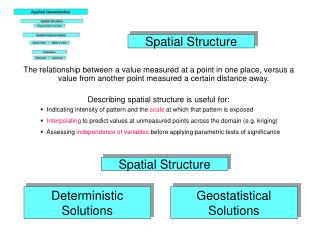
1 Spatial structure: point distribution, postplots, quantile plots Examples Distribution over the space: Scatterplot Symbol size/color reflects attribute value: Postplot Contrasting size or color: Quantile plot
2 Visualizing a regional trend Examples Here we are concerned with the formof the surface First-order: linear surface Second-order: paraboloid, bowl (lowest in the middle) or dome (highest in the middle) • Higher-order: surface has saddle points or folds
3 Local spatial dependence: Point-pairs, h-scatterplots, variogram cloud, experimental variogram • points in a dataset • (uniquepoint-pairs • The distanceand directionbetween points in geographic space • The attribute values of points in feature space • h-scatterplots • X-axisThe attribute value at a point; • Y-axisThe attribute value at a second point, at some defined distance (and possibly direction, to be discussed as anisotropy, below), from the first point. • The combination of distance and direction is called the separationvector • A bin (a lag): a rangeof distances and directions
If there is no relation between the values at the separation, the h-scatterplot will be a diffuse cloud with a low correlation coefficient. • If there is a strong relation between the values at the separation, the h-scatterplot will be close to the 1:1 line with a high correlation coefficient.
The cloud of point pairs becomes more diffuse as the separation distance increases.
Variogram / semivariogram: The most common way to visualize local spatial dependence • Semivariance: a mathematical measure of the difference between the two points in a point-pair where is a geographic point and is its attribute value. • Variogramcloud: a graph showing semivariances between all point-pairs • X-axis: The separation distance within the point-pair • Y-axis: The semivariance
Examples of a variogram cloud Left: separations to 2 km; Right: separations to 200 m Clearly, the variogram cloud gives too much information. If there is a relation between separation and semivariance, it is hard to see. The usual way to visualize this is by groupingthe point-pairs into lagsor binsaccording to some separation range, and computing some representative semivariancefor the entire lag.
Empirical variogram: Group the separations into lags (separation bins), then compute the averagesemivariance of all the point-pairs in the bin. Below the empirical variogram by Isaaks & Srivastava (1990): • is the number of point pairs separated by vector • is the distance between points and • the notation reads pairs of points indexed as and , such that… • means that this point-pair has the separation vector. In practice has some small range, the bin. Compared to Semivariance:
Another form of empirical variogram • is the number of point pairs separated by vector , in practice with some range (the range is a bin) Compared to Semivariance:
Defining the bins • There are some practical considerations, just like defining bins for a histogram: • Each bin should have enough points to give a robust estimate of the representative semivariance; otherwise the variogram is erratic; • If a bin is too wide, the theoretical variogram model will be hard to estimate and fit; • The largest separation should not exceed halfthe longest separation in the dataset; • In general the largest separation should be somewhat shorter, since it is the localspatial dependence which is most interesting. • All computer programs that compute variograms use some defaultsfor the largest separation and number of bins; gstatuses 1/3 of the longest separation, and divides this into 15 equal-width bins.
Empirical variogram of , Jura soil samples • Sill: maximum semi-variance -- represents variability in the absence of spatial dependence • Range: separation between point-pairs at which the sill is reached -- distance at which there is no evidence of spatial dependence • Nugget: semi-variance as the separation approaches zero -- represents variability at a point that can't be explained by spatial structure
Variograms of , Meuse soil pollution with different bin widths • A set of points can be displayed with many bin widths. General rule for bin width: • as narrow as possible (detail) without “too much” noise; • and with sufficient point-pairs per bin (> 100, preferably > 200)
4 Visualizing anisotropy • Isotropicor omnidirectional: spatial dependence is the same in all directions from a point • Anisotropy: Variation may depend on direction, not just distance • Directional variograms: consider points separated by a distance and in a given direction • Variogram surface / variogram map: Each grid cell shows the semivariance at a given distance and direction separation Variogram surface showing isotropy Variogram surface showing anisotropy
directional variogram • These parameters must be specified: • Maximum distance, maximum separation; • Direction of the major or minor axis in 1st quadrant • Tolerance: Degrees on either side of the direction • Band width: width of bin Directional variograms of , Meuse soil samples > plot(variogram(log(zinc) ~ 1, + meuse, alpha = c(30, 120), + cutoff = 1600), + main = "Directional Variograms, + Meuse River, log(zinc)", + sub = "Azimuth 30N (left), + 120N (right)", pl = T, + pch = 20, col = "blue") Azimuth 30N Azimuth 120N
Today: Modeling spatial structure from point samples
Acknowledgements • This lecture is partly based on: • Rossiter, D.G., 2012. Modeling spatial structurefrom point samples. Lecture in distance course Applied Geostatistics. ITC, University of Twente
Contents • Trend surfaces • Theory of random fields • Models of spatial covariance • Variogramanalysis; variogram model fitting
We often have a set of point observations (with some spatial support around the “point”). From these we usually want to: • identifythe nature of any spatial structure of one or more feature-space attributes measured at each observation point; • inferwhat spatial processes caused the observed structure; • interpolate(predict) the attribute at unsampledlocations, often on a regular grid to cover an entire study area. • We divide this into two types of processes: • Regional, also called global by contrast to the next; the process operates over an entire region; • Local: the process operates over some neighborhood (“range”) beyond which there is no influence.
1 Trend surfaces • Regional processes operate over an entire region; that is, one mathematical model is used to describe such a process. • The most common regional model is the trend surface.
Regional models • Theory: The attribute value depends on relative geographic position within a spatial field • That is, the process that affected the attribute value operates over the whole region; it has one cause • Example: thickness of a layer of volcanic ash over a buried soil: one source of ash (a volcano), spread by prevailing winds; therefore one process • Since there is only one process (“global”), all sample points are used to fit the model. • Note: Sometimes the same model form is fitted piecewise over the region, e.g. in moving trend surfaces or splines; but we will ignore that for now.
There are many mathematical forms for a regional trend. We will see the most common, namely the polynomial trend surface. • However, you should be aware that there are other forms to model surfaces. In last lecture we talked about forms of trend surfaces, now we see the mathematical models behind them
Trend surfaces • A mathematical model of a regional trend • The value of a variable at each point depends only on its coordinatesand parameters of a fitted surface • This is modeled with a smooth function of position; in 2D this is: where is the attribute value and are the two coordinates, e.g. UTM E and N. • The function is generally differentiableat least twice, to give slopes and curvatures. • When this function is computed on a regular grid, the result is called a trend surface.
Polynomial trend surfaces • The most common trend surface functions are polynomialsin the coordinates. These have some good mathematical properties: • They are differentiableto any degree (of course, beyond the degree of the polynomial the derivative is zero). • They are easy to fitusing some variety of least-squares. • The simplest trend is the plane, also known as the first ordertrend:
General polynomial trend surfaces • General form: a surface of order : • Example: full 2nd order: • Order should be suggested by the process • One-way trend: 1st order (plane) • Dome or depression: 2nd order • Folded structure: Higher orders, depending on number of inflection points • Higher orders always give better fits to the data, but beware that you may be fitting noise, not structure; use the adjusted or similar to evaluate.
Fitting trend surfaces • The trend surface is modeled by linear regression with coordinatesas the predictor variables, using data from all sample points. • In ordinary linear regression, all samples participate equally in the prediction • The goodness of fit of the trend surface to the sample is measured by the residual sum of squares, or, equivalently, the of the regression. • The same cautions apply as in feature-space regression analysis! • Ordinary Least Squares (OLS) is commonly used to compute the regression coefficients. • Note: OLS is not really correct, since it ignores possible correlation among closely-spaced samples; better is Generalized Least Squares (GLS); that is an advanced topic, see Regression Kriging
In the previous lecture and exercise (“visualization”) we computed and displayed first- and second-order trend surfaces for subsoil clay content in a region of southern Cameroon. • However, we didn't see how to model the trend with linear regression, nor how to evaluate the model. • To refresh your memory, the next two slides are the two computed surfaces, then we examine the models behind them, and how to interpret the models and fit.
Computing a trend surface model by ordinary least squares regression • We use the Cameroon soils data of Yemefacket al. (Geoderma, 125:117) • Each observation has two UTM coordinates and two attributes: • We use the R lm(“linear models”) method; all statistical packages have an equivalent comment to compute an ordinary least-squares (OLS) fit: ts1<-lm(clay35~UTM_E + UTM_N, data=tcp) • The model formula clay35~UTM_E + UTM_N specifies the functional form, in this case a dependency on the two coordinates.
The result of this computation is a fitted linear regression of the attribute(here, clay content) on the predictors, which are the grid coordinates. • R gives us the following summary table (summary(ts1)); other statistics packages have something quite similar:
Interpretation of the linear model output • In the summary of the linear model we see: • Residuals*: Lack of fit of individual observations; here from about -31.6 to +20.5 percent clay; • Coefficients: Multipliers of each term in the polynomial; here for every meter East, the clay content increases by 0.00065%, i.e. 0.65% per km • Adjusted R-squared: Proportion of variance explained by the model, here about 50%. • Recall: The “adjusted” decreases the apparent , computed from the Analysis of Variance (ANOVA) table, to account for the number of predictive factors: where is the number of observation and is the number of coefficients. * The error of an observed value is the deviation of the observed value from the (unobservable) true function value, while the residual of an observed value is the difference between the observed value and the estimated function value (c. Wikipedia).
Evaluating a trend surface fit (1) • The same tools available for any linear regression are available here: • Numericalmeasures: • Adjusted: Proportion of variance explained by the model • Residuals • Graphical method (1): “1:1” plots: Fittedvs. observedvalues • Ideally all points should fall on the 1:1 line • If not all on line, equally-spread on both sides • If there is a “curve” apparent, probably need a higher-order polynomial
Evaluating a trend surface fit (2) • Graphical method (2): Diagnostic plots of residuals • These show whether the residuals satisfy the model assumption; in particular, they should be normally distributed • Fittedvalues vs. residuals: residuals should show no pattern • if they are more variable in some part of the range then you have heteroscedasticityand need a variance-stabilizing transformation • if they are mostly on one side of the 0-axis in some range you probably need a higher-order polynomial or non-linear model. • Quantile-quantile (Q-Q) plot of residuals: compares theoretical quantiles of a normal distribution with actual quantiles • all points should be on the line • should be denser in the center (median) and spread out at the two ends. • See a good regression text for more information, e.g. Fox, J. (1997). Applied regression analysis, linear models, and related methods. Newbury Park: Sage.
Diagnostic plots from linear regression • Fitted values vs. residuals: There are slightly more values below the 0-axis • Marked as being outliers of the linear model: 84 and 145 (very large negative residuals, i.e. actual much less than fitted); 2 (very large positive residual, actual much higher than fitted)
Computing a higher-order trend surface • Some trends require a higher order than a simple plane. They are fit in the same way as the first-order surface, but include higher powers of the coordinates as predictors. • In the present example it is clear from the surface/post-plot and the regression diagnostics that a first-order surface was not satisfactory. So we compute with the square of the coordinates and their cross-product included in the model, and get the following summary:
Interpretation of the polynomial model output • Residuals:Lack of fit of individual observations; here from -29.5 to +20.8 percent clay; about the same as for the first-order surface • Coefficients:Multipliers of each term in the polynomial, but now there are four: the coordinates and their squares, and of course the intercept. • Statistical significance of coefficients: The listed Pr(>|t|) gives the probability that the coefficient is in fact 0 (the null hypothesis), i.e. that it contributes nothing to the model. In this example the cross-product of the coordinates, i.e. I(UTM_E * UTM_N) is almost surely not necessary and the model can be re-fit without it. • Adjusted R-squared: Proportion of variance explained by the model, here about 52%, a slight improvement over the first-order surface • We evaluate the fit with the same diagnostics as in the first-order model.
Fitted vs. observed (1:1) plots There is only a 2% improvement in adjusted R2 (from 0.499 to 0.519)
Diagnostic plots from first- and second-order linear regressions
In summary, there are some processes that operate over an entire region of interest. These can lead to regional trends, where an attribute can be modeled as a function of the geographic coordinates. • A common functional form is the polynomial trend surface, which is fit to the data by some form of regression, often ordinary least squares. • However, as the example in this section showed, the regional trend often does not explain all the variation. • We now look at the other side, namely processes that operate only locally. Later we will see how to combine the two types of spatial structure.
2 Theory of random fields • Now we turn to local spatial dependence. The idea here is that there is a local process that causes nearby points to be “similar”. We will see how to quantify this and use it in modeling and prediction. • But first we need some theoretical background: a brief explanation the theory underlying optimal geostatistical estimation by kriging. The presentation is based on R. Webster and M. Oliver, 2001 Geostatistics for environmental scientists, Chichester etc.: John Wiley & Sons.
This is difficult material, mainly because it is abstract and indeed quite strange at first glance. Some modelers do not accept it at all! Our position is that this model of an essentially unobservable hypothetical process has proven to be very useful in practice. • The important point here is that we believe that observed values in space are the result of some spatially-correlatedprocess (to be explained) which we can infer from the observations. • But be aware: as with many models, it is impossible to verify the underlying assumptions. If you feel uncomfortable with this, you are not alone!
Modeling spatial variation as a random process • Notation: A point in space of any dimension is symbolized by a bold-face letter, e.g. . • Key idea: The observed attribute values are only one of many possible realizationsof a random process (also called a “stochastic” process) • This random processes is spatially auto-correlated (to be explained below), so that attribute values are somewhat dependent. • At each point , an observed valueis one possibility of a random variable • There is only one reality (which is sampled), but it is one realization of a processthat could have produced many realities. • CDF: for a given value : • the probability governs the random process; this is where we can model spatial dependence CDF: cumulative distribution function
Random functions • Each point has its ownrandom process, but these all have the same form (same kind of randomness) • However, there may be spatial dependence among points, which are therefore not independent • As a whole, they make up a stochastic process over the whole field • i.e. the observed values are assumed to result from some random process but one that respects certain restrictions, in particular spatial dependence • The set of values of the random variable in the spatial field: is called a regionalized variable • This variable is doubly infinite: (1) number of points; (2) possible values at each point
The above is a difficult point for most people to grasp. It's always easier to visualize, so the next slide shows four different realizations of the same random field. • These are all equally-probablerealizations of , given a known spatially-dependent stochastic process. • (For later reference: this is a 256 x 256 grid, with a Spherical model of spatial dependence with range 25)