Download
1 / 26
260 likes | 435 Vues
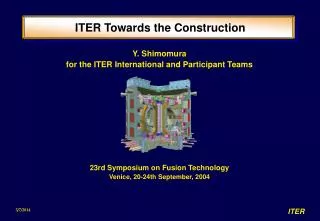
Neutron yield measurements and absolute calibration issues in JET towards ITER requirements. S. Popovichev UKAEA Fusion, Culham Science Centre, Abingdon, UK in collaboration with A. Murari, L. Bertalot, G. Bonheure, S.Conroy, M.J. Loughlin and contributors to the EFDA-JET workprogramme.

E N D
Neutron yield measurements and absolute calibration issues in JET towards ITER requirements S. Popovichev UKAEA Fusion, Culham Science Centre, Abingdon, UK in collaboration with A. Murari, L. Bertalot, G. Bonheure, S.Conroy, M.J. Loughlin and contributors to the EFDA-JET workprogramme S. Popovichev10th Meeting of ITPA Topical Group on Diagnostics, Moscow, 10-14 April 2006
Outline: • Introduction: ITER & JET • JET Neutron Yield Monitors: • Time-Resolved • Time-Integrated (Activation system) • Calibrations issues, results, challenges • Summary S. Popovichev10th Meeting of ITPA Topical Group on Diagnostics, Moscow, 10-14 April 2006
Introduction: ITER & JET • Requirements, needs, potential solutions and status of ITER NFM has been already reported and published repeatedly, e.g. see: G.J.Sadler, J.M.Adams et al., Varenna, 1997 M. Sasao, A.V. Krasilnikov, T. Nishitani et. al., Plasma Phys.Control.Fusion, 46 (2004), S107 K. Asai, T. Iguchi, K. Watanabe et. al., RSI, vol.75 (10), 2004 A.V. Krasilnikov, M. Sasao, Yu. A. Kaschuck et. al., NF, 45 (2005), 1503 (see also materials of 9th ITPA) • The definition, design, developments, integration of neutron systems into ITER is already under way to a large extent. S. Popovichev10th Meeting of ITPA Topical Group on Diagnostics, Moscow, 10-14 April 2006
Introduction: ITER & JET • The complexity of choice and design of neutron yield detectors in ITER comes from very wide range of machine operation • (in situ calibration; H, DD, Trace T and full DT (50:50) plasma) • The use of different fuels leads to: • large variation in neutron flux (about 10 orders!) • changes in neutron energy spectra, e.g.as does the use of different plasma heating techniques. Ii is very difficult to satisfy all requirements for neutron flux detectors using one type of detector. ******** Possible solution is to have several detectors and independent different techniques which will complement each other. JET is a good example of this! S. Popovichev10th Meeting of ITPA Topical Group on Diagnostics, Moscow, 10-14 April 2006
Introduction: ITER & JET The JET tokamak is the most suitable test bed for the development of neutron systems due to: • its plasma parameters (and it is a ITER-like, ~1/3 of ITER) • unique capability to operate with DT fuel. • JET has a comprehensive set of absolutely calibrated neutron diagnostics making possible the cross check between “new” and JET systems. Neutron systems proposed and designed for ITER could be tested at JET. JET has already started a number of interesting developments/tests, e.g. testing and successful operation of NDD & Stilbene detectors(RF) and NE213 & CVD (ENEA, Italy) detectors during TTE-2003 and coming campaigns). S. Popovichev10th Meeting of ITPA Topical Group on Diagnostics, Moscow, 10-14 April 2006
JET Neutron Yield Monitors: • Time-Resolved: • Total (2.5 MeV + 14 MeV) Neutron Yield • 14 MeV Neutron Yield • Time-Integrated(Activation system): • 2.5 MeV and 14 MeV Neutron Yield S. Popovichev10th Meeting of ITPA Topical Group on Diagnostics, Moscow, 10-14 April 2006
JET Time-resolved Total Neutron Yield Monitor Detectors : • 3 pairs of fission chambers - U235&U238 • Operate in both pulse counting and current modes • Usable for neutron emissions from 1010to 1020 n/s • Relatively insensitive to the neutron energy • Absolutely calibrated to 10% (in-situ using 252Cf source and by activation technique) DAC system consists of: • 12 “slow” data-channels (typically D t ~ 5-10 ms) • which suitably merged to single time-trace • 3 “fast” windows (typically D t ~ 150 ms, could be down to 20 ms) S. Popovichev10th Meeting of ITPA Topical Group on Diagnostics, Moscow, 10-14 April 2006
14 MeV Neutron Yield Monitors • The Si diode detectors are employed at JET for this purpose since 1987. • Several Si diodes with different surface area are installed in different locations at JET allowing the 14 MeV neutron rates from 1013 n/s up to 1018 n/s to be measured. • The detection sensitivities of such kind of system is ~ 1 count per 1010_1012 JET 14 MeV neutron (depends on an area of diode, location in the machine, energy threshold used) • The Natural Diamond (NDD) and Chemical Vapor Deposited Diamond detectors have been successfully tested at JET during TTE campaign in 2003. • At present three CVD (to measure total and 14 MeV neutron yield) and one NDD are installed at JET. S. Popovichev10th Meeting of ITPA Topical Group on Diagnostics, Moscow, 10-14 April 2006
14 MeV Neutron Yield Monitors • Three CVD diamonds are installed in 2005: • A 2.5 MeV neutron monitor is built using a Polycrystalline CVD covered with a 6LiF film detecting the alphas emitted by thermal neutron capture in 6Li. A neutron moderator surrounds the detector. CVD is located at the level of the torus midline, approximately 7.8 m from the plasma centre. • A 14 MeV neutron spectrometer is built using a single crystal diamond. It is sitting near Main Vertical Port, approximately 4 m from the centre of plasma. • A 14 MeV neutron monitor built using a high efficiency Polycrystalline CVD which is connected to a fast electronic chain. Location is near Main Horizontal port at the level of plasma midplane, approximately 6 m from the plasma centre. One NDD is installed in the Torus Hall close to Main Horizontal port (the same detector box as for CVD3). S. Popovichev10th Meeting of ITPA Topical Group on Diagnostics, Moscow, 10-14 April 2006
Activation Technique • It is based on the analysis of the radioactivity induced by the plasma neutrons in selected samples. • Primary purposes: • a reliable calibration of fission chambers • to measure the 14 MeV neutron emission. • Careful neutron transport calculations are needed to relate the total neutron yield from the plasma to the neutron fluence at the sample position. • At JET, two codes have been used for transport calculations. • Only after several iterations and extended investigations the agreement between them was achieved. • To simplify the neutron transport problem is beneficial to choose irradiation ends as close as possible to the plasma (e.g. JET 3Upper irradiation end) S. Popovichev10th Meeting of ITPA Topical Group on Diagnostics, Moscow, 10-14 April 2006
JET Activation System • conventional gamma-radiation measurements >>> most widely used reactions at JET: DD neutrons - 115In(n,n’)115mIn, DT neutrons - 28Si (n,p)28AL, 63Cu(n,2n)62Cu, 56Fe(n,p)56Mn >>>detectors : 3 NaI, HPGe (absolutely calibrated) • delayed neutron counting of beta-delayed neutrons from fission events (235U,238U,232Th) >>>usually used to measure DD neutron yield on conditions that YDD>> YDT >>>detector system: 2 stations with six 3He counters • At JET - 8Irradiation ends located: in 5octants ---> test of toroidal symmetry of neutron emission withinboard and outboard positions -> radial plasma position andupper and lower positions --> vertical plasma displacement • The accuracy of the yields measurements is typically ~ 8-10% for both DD and DT neutrons (7% as best for delayed neutrons) S. Popovichev10th Meeting of ITPA Topical Group on Diagnostics, Moscow, 10-14 April 2006
Introduction: ITER & JET • JET Neutron Yield Monitors: • Time-Resolved • Time-Integrated (Activation system) • Calibrations issues, results, challenges • Summary S. Popovichev10th Meeting of ITPA Topical Group on Diagnostics, Moscow, 10-14 April 2006
Calibration issues (1) • The absolute calibration of FCs was first obtained in 1984 in situ using 252Cf source. • Angular distribution of FC response were measured for 4 radii R values • (ttotal meas > 10h). • The overall accuracy of the calibration ±10%. • Second in situ run of calibration was performed in 1985 after some changes were made to the diagnostic disposition. • The insensitivity to the neutron energy spectrum was also demonstrated using other sources (241Am-Be and 14 MeV neutron generator). • Although this results was recognized to be appropriate only for those machine conditions at the calibration time. • Later, activation measurements were used to deliver the absolute calibration with an improved accuracy ~ ±7%. • Those measurements indicated that with the installation of new heavy equipment near JET main access ports, the response of individual FC is changing considerably over the time and had become dependent on the neutron energy spectrum. S. Popovichev10th Meeting of ITPA Topical Group on Diagnostics, Moscow, 10-14 April 2006
Calibrations issues (2) • Fission chambers are checked against each other on the shot by shot basis and an alarm is raised if the response of one of the detectors by more than ~5% from their average. • The FC monitor data are always cross checked against the data from other available independent neutron yield measurements (e.g. Neutron Profile Monitor , MPR ) • Comparison with code predictions (e.g. TRANSP) and in-vessel dose rate calculations and measurements also confirms the adequacy of neutron calibration procedure. S. Popovichev10th Meeting of ITPA Topical Group on Diagnostics, Moscow, 10-14 April 2006
Calibration results (1) FCs calibration check during JET TTE campaign 2003 Yn total (DD+DT) FCs, neutron/shot Yn total (DD+DT) from activation, neutron/shot S. Popovichev10th Meeting of ITPA Topical Group on Diagnostics, Moscow, 10-14 April 2006
Si diodes calibration for JET TTE campaign 2003 Activation Y14, neutron/shot Si diode, counts/shot Calibration results (2) S. Popovichev10th Meeting of ITPA Topical Group on Diagnostics, Moscow, 10-14 April 2006
Calibration results (3) NDD and CVD Diamond detectors response to Tritium JET shots ## 61084-61236 S. Popovichev10th Meeting of ITPA Topical Group on Diagnostics, Moscow, 10-14 April 2006
Yn 14 Neutron Profile monitor, n/shot Yn 14 (Si diodes), neutrons/shot Calibration results (4) Comparison of 14 MeV Yn measured by Neutron Profile Monitor (Bicron detectors) and MPR with Si diodes data (~450 TTE shots) Neutron Profile Monitor Magnetic Proton Recoil Spectrometer S. Popovichev10th Meeting of ITPA Topical Group on Diagnostics, Moscow, 10-14 April 2006
Calibration results (5) Comparison between FC(red) and TRANSP (blue) Two shots with T gas puff and different DD/DT ratios: 61097: large T influx 61374: small T influx Yn total (DD+DT) FCs, 10^16 n/shot Time S. Popovichev10th Meeting of ITPA Topical Group on Diagnostics, Moscow, 10-14 April 2006
Challenges… FCs Hardware - Did not have serious technical/hardware problems so far. 14 MeV neutron monitors. There are two most serious problems: • radiation damage of Si diodes (fluence limit of ~ 1012 n/cm2), the detectors have to be replaced periodically; • can be used only in pulse-counting mode so the dynamic range is restricted(so saturation issues arise). Therefore JET TTE solution of this problem was to install : several (4) Si diodes with different sensitivities and CVD & NDD detectors with high radiation hardness. S. Popovichev10th Meeting of ITPA Topical Group on Diagnostics, Moscow, 10-14 April 2006
Challenges… FCs Calibrations : • fission chamber calibration can change considerably with installation of the new equipment near to FC (e.g. ~17.5% change because of installation of EFCC in 2002) • the individualfission chamber calibration factor are quite sensitive to the neutron energy spectrum (e.g. different response to DD and DT neutrons). It has been noticedduring PTE1 (1991), DTE1 (1997) and TTE (2003). ExtensiveMCNP calculations are needed to quantify these effects. S. Popovichev10th Meeting of ITPA Topical Group on Diagnostics, Moscow, 10-14 April 2006
JET FCs TTE 2003 Calibrations FCs Total neutron yield, (Rn< 1016 n/s i.e.mostly DD neutrons) Total neutron yield, individual FCs, n/shot Total neutron yield, (FCs average = Activation), n/shot S. Popovichev10th Meeting of ITPA Topical Group on Diagnostics, Moscow, 10-14 April 2006
JET FCs TTE 2003 Calibrations FCs Total neutron yield, (Rn> 1016 n/s) i.e ~50-50% DD & DT neutrons) Total neutron yield, individual FCs, n/shot Total neutron yield (FCs average = Activation), n/shot S. Popovichev10th Meeting of ITPA Topical Group on Diagnostics, Moscow, 10-14 April 2006
JET Fission Chambers response 235U counter response – linear energy scale 238U counter response – 19.4 cm Pb shield S. Popovichev10th Meeting of ITPA Topical Group on Diagnostics, Moscow, 10-14 April 2006
Summary • The neutron emission from JET is reliably measured by a comprehensive set of neutron yield monitors available. • These monitors can operate usefully over a wide range of neutron intensities (FCs are covering 10 decades). • The absolute calibration relies on activation measurements and is performed to an accuracy of ~ 10%. • Monte Carlo transport calculations have to be always performed in support (and understanding) of the calibration data. S. Popovichev10th Meeting of ITPA Topical Group on Diagnostics, Moscow, 10-14 April 2006
Issued to be addressed: • It will need to perform the Monte Carlo Neutron transport calculations with detailed ITER model will be needed (especially for activation measurements). • Particular attention has to be given to the calibration methods/procedures of ITER neutron diagnostic (several different methods should be used) >> Direct calibration by neutron generator is practical only before start-up when the ITER vessel will be cold. Will be this calibration valid forhot vessel? >> An activation system for in situ and for routine cross calibration is strongly recommended. What else? Time for discussion! S. Popovichev10th Meeting of ITPA Topical Group on Diagnostics, Moscow, 10-14 April 2006