Download

1 / 23
230 likes | 356 Vues
This presentation details the structural design and engineering analysis of Park Potomac Office Building E, conducted as a senior thesis by Kyle Wagner under the guidance of Prof. Kevin Parfitt. It covers the existing structural system, problem identification, proposed solutions to reduce building self-weight using steel structures, and a comprehensive structural depth study. Additionally, it includes cost and schedule analyses, design goals, and concludes with acknowledgments and a question-and-answer session to foster discussion on the project's complexities and innovations.

E N D
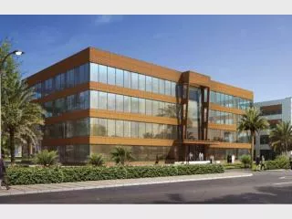
Park Potomac Office Building “E” Kyle Wagner l Structural Option AE Senior Thesis l Spring 2010 Faculty Consultant l Prof. Kevin Parfitt
Project Information • Existing Structural System • Problem Statement and Solution • Structural Depth Study • Cost and Schedule Analysis • Additional Topics • Conclusions • Acknowledgements • Questions and Comments Presentation Overview
Presentation Overview • Project Information • Existing Structural System • Problem Statement and Solution • Structural Depth Study • Cost and Schedule Analysis • Additional Topics • Conclusions • Acknowledgements • Questions and Comments • Located off I-270 in Potomac, MD Project Information • Part of Park Potomac Place • Townhomes, Office Space, Retail, Dining • Prominent location within Community • Focal point from Cadbury Ave. • Face of community from I-270 View from Cadbury Ave www.parkpotomacplace.com
Presentation Overview • Project Information • Existing Structural System • Problem Statement and Solution • Structural Depth Study • Cost and Schedule Analysis • Additional Topics • Conclusions • Acknowledgements • Questions and Comments • Two levels mostly underground parking • 100,000+ SF each Project Information • Seven levels of mostly office space • Approx. 25,000 SF each North Entrance to Parking Levels Building Footprint
Presentation Overview • Project Information • Existing Structural System • Problem Statement and Solution • Structural Depth Study • Cost and Schedule Analysis • Additional Topics • Conclusions • Acknowledgements • Questions and Comments • Underground Parking all Cast-in-place concrete • 7” Thick slab post-tensioned in N-S direction Existing Structural System • 72” x 20” D Beams post-tensioned in E-W direction • Concrete Moment Frames in both directions • Long Spans accomplished • Flexibility for Tenant • 12’ Cantilever at N, S ends Existing Structural System
Presentation Overview • Project Information • Existing Structural System • Problem Statement and Solution • Structural Depth Study • Cost and Schedule Analysis • Additional Topics • Conclusions • Acknowledgements • Questions and Comments • Concrete structure results in large building self weight Problem Statement • Larger gravity members result • Large mat foundations at soil level • Central Foundation 52’ x 64’ x 60” Deep • Longer schedule duration from concrete construction • End Result: Negative Cost and Schedule Implications Existing Foundation Plan
Presentation Overview • Project Information • Existing Structural System • Problem Statement and Solution • Structural Depth Study • Cost and Schedule Analysis • Additional Topics • Conclusions • Acknowledgements • Questions and Comments • Reduce building self weight by utilizing a steel structure Problem Solution • Composite Beams and lightweight concrete used • To maintain integrity of existing design: • Maintain current column layout • Maintain current ceiling heights in Tenant Spaces • Maintain current MEP Spaces • Braced Frames used to resist lateral forces • Steel construction likely to reduce construction schedule • Parking levels will remain unchanged
Presentation Overview • Project Information • Existing Structural System • Problem Statement and Solution • Structural Depth Study • Cost and Schedule Analysis • Additional Topics • Conclusions • Acknowledgements • Questions and Comments • Reduce building self weight Project Goals • Maintain integrity of tenant spaces • Reduce overall cost • Reduce schedule duration
Presentation Overview • Project Information • Existing Structural System • Problem Statement and Solution • Structural Depth Study • Cost and Schedule Analysis • Additional Topics • Conclusions • Acknowledgements • Questions and Comments • Design Loads • ASCE 7-05 Design Loads • Superimposed Dead Loads • 5 psf Floor • 10 psf Roof • Flat Roof Snow Load • 21 psf Live Load Values
Presentation Overview • Project Information • Existing Structural System • Problem Statement and Solution • Structural Depth Study • Cost and Schedule Analysis • Additional Topics • Conclusions • Acknowledgements • Questions and Comments • 5 ½” Thick Slab on 2”, 18 Gage Metal Decking • Provides adequate 2 hour fire rating between floors Gravity System Design • Beams spacing does not exceed 10’ • Unshored • Minimize number of beams required • Columns spliced every other floor Typical Floor Layout RAM Model
Moment connection at interior to balance moment at column Presentation Overview • Project Information • Existing Structural System • Problem Statement and Solution • Structural Depth Study • Cost and Schedule Analysis • Additional Topics • Conclusions • Acknowledgements • Questions and Comments • 12’ Cantilever on North and South Ends • Unobstructed glass around building corners Cantilevered Ends • Moment from cantilever: 575 ft-k • Moment from interior: 376 ft-k • Four beams used to transfer load back to columns • Moment to column: 199 ft-k • Design for moment and axial due to gravity load • Beam required: • W18x55 • Final Design shown at right
Presentation Overview • Project Information • Existing Structural System • Problem Statement and Solution • Structural Depth Study • Cost and Schedule Analysis • Additional Topics • Conclusions • Acknowledgements • Questions and Comments • Existing post-tensioned system • Maintain ceiling heights and MEP Spaces • 20” depth at beams Floor Depth Comparison • Steel Design • Increase overall building height • Deepest Beam: W27x84 • No code restrictions • Increase by 12” per floor • Overall height increase by 7’ • Recalculate lateral loads • Floor Depth Approx. 32”
Presentation Overview • Project Information • Existing Structural System • Problem Statement and Solution • Structural Depth Study • Cost and Schedule Analysis • Additional Topics • Conclusions • Acknowledgements • Questions and Comments • Wind: Method 2 of ASCE 7-05 Chapter 6 Lateral Loads • Assume wind negligible beneath plaza level • Seismic: ELFP of ASCE 7-05 Chapter 11 • Seismic Design Category B • Seismic Base Level taken at plaza level • Wind controlled for strength and serviceability
Presentation Overview • Project Information • Existing Structural System • Problem Statement and Solution • Structural Depth Study • Cost and Schedule Analysis • Additional Topics • Conclusions • Acknowledgements • Questions and Comments • 7 Load combinations, 4 wind cases, accidental torsion (5% ecc.) due to seismic all manually included ETABS Model • Floors modeled as rigid diaphragms • Loads distributed based on relative stiffnesses of frames • Only lateral system modeled • Gravity loads applied using additional area mass to diaphragm ETABS Model
Presentation Overview • Project Information • Existing Structural System • Problem Statement and Solution • Structural Depth Study • Cost and Schedule Analysis • Additional Topics • Conclusions • Acknowledgements • Questions and Comments • Symmetry in Geometry and Stiffness Braced Frame Design • Loads distributed evenly to each frame • SAP used to calculate forces in braces for critical load combination • Critical load combination used to design columns • Final Brace Frame Design shown at right • E-W Frames larger than N-S Frames N-S Braced Frame E-W Braced Frame
Presentation Overview • Project Information • Existing Structural System • Problem Statement and Solution • Structural Depth Study • Cost and Schedule Analysis • Additional Topics • Conclusions • Acknowledgements • Questions and Comments • Primary controlling load case was 0.9D+1.6W Lateral Analysis • Controlling wind case was Wind Case 1 • Center of mass and rigidity both at geometric center • Overall building torsion was negliglible • Wind drift within L/400 • Seismic drift found to be well within limitations
Presentation Overview • Project Information • Existing Structural System • Problem Statement and Solution • Structural Depth Study • Cost and Schedule Analysis • Additional Topics • Conclusions • Acknowledgements • Questions and Comments Foundation Design • Existing foundations • Steel Structure Foundations • 17’ x 17’ x 34” Deep (U.N.O.)
Presentation Overview • Project Information • Existing Structural System • Problem Statement and Solution • Structural Depth Study • Cost and Schedule Analysis • Additional Topics • Conclusions • Acknowledgements • Questions and Comments • Detailed takeoffs completed for both systems Cost/ Schedule • Foundations cost reduced 78% • Total Structure cost reduced by 25% • Assuming $50 per SF of building enclosure • $224,000 additional • Final Steel cost of $20.69 per SF • Schedule predicted to be decreased by approx. 10 months • General conditions savings not factored into cost results
Presentation Overview • Project Information • Existing Structural System • Problem Statement and Solution • Structural Depth Study • Cost and Schedule Analysis • Additional Topics • Conclusions • Acknowledgements • Questions and Comments • Design of Connections • Architectural Study Additional Topics
Presentation Overview • Project Information • Existing Structural System • Problem Statement and Solution • Structural Depth Study • Cost and Schedule Analysis • Additional Topics • Conclusions • Acknowledgements • Questions and Comments • Potential to reduce floor depth • Potential to balance additional moment Further Improvements • From Earlier: • Deepest Beam: W27x84 • Unbalanced moment: 199 ft-k • Use W21 x 93 instead • Constrain 10 beams on each floor • Decreasing cantilever distance or increase moment on interior • Floor depth required: 32” 26” • Overall height increase by 3.5’, not 7’ • Much smaller columns will result
Presentation Overview • Project Information • Existing Structural System • Problem Statement and Solution • Structural Depth Study • Cost and Schedule Analysis • Additional Topics • Conclusions • Acknowledgements • Questions and Comments • Reduce building self weight Conclusions • Maintain integrity of tenant spaces • Reduce overall cost • Reduce schedule duration • Steel could have been a viable and beneficial alternative. Office Building “E”
Presentation Overview • Project Information • Existing Structural System • Problem Statement and Solution • Structural Depth Study • Cost and Schedule Analysis • Additional Topics • Conclusions • Acknowledgements • Questions and Comments A special thanks to: Acknowledgements • Frank Malits • Daniel Camp • Karl Alt PSU Architectural Engineering Faculty
Presentation Overview • Project Information • Existing Structural System • Problem Statement and Solution • Structural Depth Study • Cost and Schedule Analysis • Additional Topics • Conclusions • Acknowledgements • Questions and Comments Questions/Comments