Local Asynchronous Communication
Local Asynchronous Communication. CS442. Bitwise Data Transmission. Data transmission requires: Encoding bits as energy Transmitting energy through medium Decoding energy back into bits Energy can be electric current, radio, infrared, light, smell, etc.


Local Asynchronous Communication
E N D
Presentation Transcript
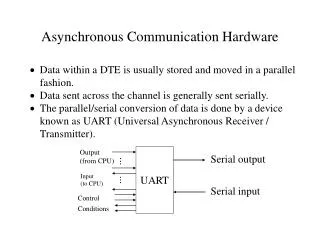
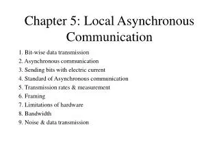
Bitwise Data Transmission • Data transmission requires: • Encoding bits as energy • Transmitting energy through medium • Decoding energy back into bits • Energy can be electric current, radio, infrared, light, smell, etc. • Transmitter and receiver must agree on encoding scheme and transmission timing
Asynchronous Transmission • One definition of asynchronous: transmitter and receiver do not explicitly coordinate each data transmission • Transmitter can wait arbitrarily long between transmissions • Used, for example, when transmitter such as a keyboard may not always have data ready to send • Asynchronous may also mean no explicit information about where data bits begin and end • E.g. when we send individual ASCII characters
Using Electric Current to Send Bits • Simple idea - use varying voltages to represent 1s and 0s • One common encoding use negative voltage for 1 and positive voltage for 0 • In following figure, transmitter puts positive voltage on line for 0 and negative voltage on line for 1
Transmission Timing Problems • Encoding scheme leaves several questions unanswered: • How long will voltage last for each bit? • How soon will next bit start? • How will the transmitter and receiver agree on timing? • Later : Self-clocking codes (e.g. Manchester Encoding) • Standards specify operation of communication systems • Devices from different vendors that adhere to the standard can interoperate • Example organizations: • International Telecommunications Union (ITU) • Electronic Industries Association (EIA) • Institute for Electrical and Electronics Engineers (IEEE)
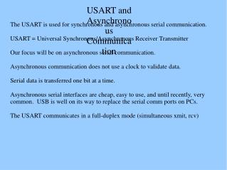
RS-232 • Standard for transfer of characters across copper wire • Produced by EIA • Full name is RS-232-C • RS-232 defines serial, asynchronous communication • Serial - bits are encoded and transmitted one at a time (as opposed to parallel transmission) • Asynchronous - characters can be sent at any time and bits are not individually synchronized
Details of RS-232 • Components of standard: • Connection must be less than 50 feet • Data represented by voltages between +15v and -15v • 25-pin connector, with specific signals such as data, ground and control assigned to designated pins • Specifies transmission of characters between, e.g., a terminal and a modem • Transmitter never leaves wire at 0v; when idle, transmitter puts negative voltage (a 1) on the wire
Identifying asynchronous characters • Transmitter indicates start of next character by transmitting a one • Receiver can detect transition as start of character • Extra one called the start bit • Transmitter must leave wire idle so receiver can detect transition marking beginning of next character • Transmitter sends a zero after each character • Extra zero call the stop bit • Thus, character represented by 7 data bits requires transmission of 9 bits across the wire
Start, Stop Bits Typically one of the data bits might be a parity bit (7N1, 8E1)…
Timing • Transmitter and receiver must agree on timing of each bit • Agreement accomplished by choosing transmission rate • Measured in bits per second • Detection of start bit indicates to receiver when subsequent bits will arrive • Hardware can usually be configured to select matching bit rates • Switch settings • Software • Autodetection
Transmission Rates • Baud rate measures number of signal changes per second • Bits per second measures number of bits transmitted per second • In RS-232, each signal change represents one bit, so baud rate and bits per second are equal • If each signal change represents more than one bit, bits per second may be greater than baud rate • This is the case with modems nowadays! • More on this when we look at modulation
Framing • Start and stop bits represent framing of each character • If transmitter and reciver are using different speeds, stop bit will not be received at the expected time • Problem is called a framing error • RS-232 devices may send an intentional framing error called a BREAK
Duplex • Two endpoints may send data simultaneously - full-duplex communication • Requires an electrical path in each direction • If only one endpoint may send data – half-duplex communications or simplex • Pin 2 - Receive (RxD) • Pin 3 - Transmit (TxD) • Pin 4 - Ready to send (RTS) • Pin 5 - Clear to send (CTS) • Pin 7 - Ground
Limitations on Transmission • Limitations on wires makes waveforms look like: • Longer wire, external interference may make signal look even worse • RS-232 standard specifies how precise a waveform the transmitter must generate, and how tolerant the receiver must be of imprecise waveform
Channel Capacity • Data rate • In bits per second • Rate at which data can be communicated • Bandwidth • In cycles per second, or Hertz • Amount of bandwidth constrained by transmitter and medium (and the feds!) • For digital data: Want as high a data rate as possible given some slice of bandwidth! Limited by the error rate
Nyquist Bandwidth(1) • If the rate of signal transmission is 2B then a signal with frequencies no greater than B is sufficient to carry the signal rate • Converse: Given a bandwidth of B, the highest signal rate that can be carried is 2B • Ex: Given 3000Hz (typical on phone lines), the capacity C of the channel is : C=2B = 6000bps
Nyquist Bandwidth(2) • Wait! But given about 3000Hz our modems go much faster than 6000bps. How? • The previous capacity assumes a binary signal element. If a signal element can represent more than one bit, the formulation becomes: • C=2B(log2M) ; M = # of signal elements • If M=32, we get C=30,000bps
Shannon’s Capacity • Shannon’s capacity includes the concept of error rates. At a given noise level, the higher the data rate, the higher the error rate. This is a theoretical maximum! • Signal to Noise Ratio: • SNR = SignalPower/NoisePower • Ratio measured at the receiver • SNRdb = 10log10(SNR) • SNR of 100 = 20 dB • SNR of 1000 = 30 dB • Capacity: • C = B*log2(1+SNR)
Shannon Capacity Examples • If voice telephone has a SNR of 30 dB and bandwidth of 3000 Hz: • C = 3000 log2(1 + 1000) = 30,000 bps • If our LAN technology has a SNR=251, B = 1Mhz • C=106*log2(252) = 8Mbps • Using Nyquist’s formula, the number of symbols we would need to transmit this data per signaling element: • 8*106 = 2*106*log2M M = 24 = 16