
Advancements in Real-Time Flood Prediction: The RAIN Sensor Network
The RAIN (Rice Atmospheric Information Network) project presents an innovative sensor network designed for real-time meteorological data collection and flood prediction. Traditional systems are often costly and lack the ability to provide immediate data. RAIN features a non-invasive, inexpensive, scalable design that employs binary frequency shift key (FSK) transmission for reliable communication. With a robust infrastructure comprising independent nodes, this network aims to deliver accurate flood warnings, enhancing safety for residents and businesses. The deployment of low-power equipment ensures an efficient and effective data gathering process.

Advancements in Real-Time Flood Prediction: The RAIN Sensor Network
E N D
Presentation Transcript
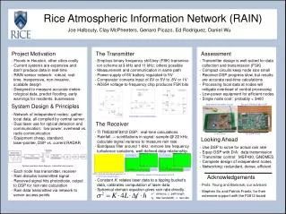
Project Motivation Rice Atmospheric Information Network (RAIN) Joe Halbouty, Clay McPheeters, Genaro Picazo, Ed Rodriguez, Daniel Wu The Transmitter Assessment • Floods in Houston, other cities costly • Current systems are expensive and • don’t produce data in real-time • RAIN sensor network: robust, real- • time, inexpensive, non-invasive, • scalable design • Designed to measure accurate meteo- • rological data, predict flooding, early • warnings for residents, businesses • Employs binary frequency shift key (FSK) transmiss- • ion scheme at 9 kHz and 11 kHz; others possible • Measurement and communication in same path • Power supply of 6V battery regulated to 5V • Comparator converts input of 0V or 5V to .8V or 1V • AD654 voltage-to-frequency chip produces FSK bits • Transmitter design is well-suited for data • collection and transmission (FSK) • Compact circuits keep node size small • Receiver DSP progress slow, but results • are accurate real-time calculations • Processing local data at nodes will • mitigate overhead of central processing • - Low-power equipment for efficient nodes • - Single node cost: probably < $400 System Design & Principles Assembled Transmitter Circuits Receiver TMS320F2812 DSP • Network of independent nodes: gather • local data, all compiled by central server • Dual laser use for optical detection and • communication: low power, overhead vs. • radio communication • Equipment cheap, standard: • laser-pointer, DSP vs. current RADAR Transmitter Circuit Schematics The Receiver • TI TMS320F2812 DSP: real-time calculations • Rainfall → scintillations in signal: sample @ 22 kHz, • calculate signal variance to measure rain rate • Bandpass filter around 1 kHz: remove low frequency • turbulence variations, well-defined data relationship 10 cm x 6 cm 13.5 cm x 7.5 cm Looking Ahead • Use DSP to solve for actual rain rate • Equip DSP with D/A: data transmission • Transmitter control: MSP430, GNOMES • Complete design of independent nodes • Networking: redundant, dense, efficient System operation block diagram: transmitter and receiver • - Each node has transmitter, receiver • - Rain disturbs transmitted signal • Received signal hits photodiode, output • to DSP for rain rate calculation • Rain data transmitted via network to • server access points DSP real-time calculated spectrum of -----10 kHz input square wave Acknowledgements Real-time spectra of filtered output on DSP • Constant K: relates laser data to a tipping bucket’s • data, calibrates computation of laser data • Spherical domain equation gives rain rate directly: • Profs. Young and Baraniuk, our advisors • Stephen So and Patrick Frantz, for their --extensive support with the F2812 board