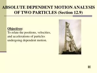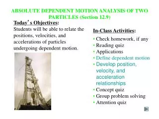
ABSOLUTE MOTION ANALYSIS (Section 16.4)
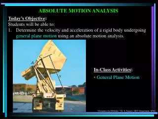
ABSOLUTE MOTION ANALYSIS (Section 16.4). Today’s Objective : Students will be able to determine the velocity and acceleration of a rigid body undergoing general plane motion using an absolute motion analysis. In-Class Activities : • Check homework, if any • Reading quiz • Applications

ABSOLUTE MOTION ANALYSIS (Section 16.4)
E N D
Presentation Transcript
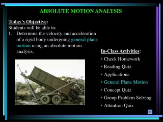
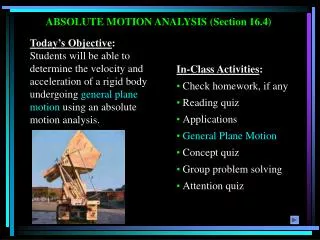
ABSOLUTE MOTION ANALYSIS (Section 16.4) Today’s Objective: Students will be able to determine the velocity and acceleration of a rigid body undergoing general plane motion using an absolute motion analysis. In-Class Activities: • Check homework, if any • Reading quiz • Applications • General Plane Motion • Concept quiz • Group problem solving • Attention quiz
APPLICATIONS The position of the piston, x, can be defined as a function of the angular position of the crank, q. By differentiating x with respect to time, the velocity of the piston can be related to the angular velocity, w, of the crank. The stroke of the piston is defined as the total distance moved by the piston as the crank angle varies from 0 to 180°. How does the length of crank AB affect the stroke?
APPLICATIONS (continued) The rolling of a cylinder is an example of general plane motion. During this motion, the cylinder rotates clockwise while it translates to the right. The position of the center, G, is related to the angular position, q, by sG = r q if the cylinder rolls without slipping. Can you relate the translational velocity of G and the angular velocity of the cylinder?
PROCEDURE FOR ANALYSIS The absolute motion analysis method (also called the parametric method) relates the position of a point, P, on a rigid body undergoing rectilinear motion to the angular position, q (parameter), of a line contained in the body. (Often this line is a link in a machine.) Once a relationship in the form of sP = f(q) is established, the velocity and acceleration of point P are obtained in terms of the angular velocity, w, and angular acceleration, a, of the rigid body by taking the first and second time derivatives of the position function. Usually the chain rule must be used when taking the derivatives of the position coordinate equation.
EXAMPLE 1 Given: Two slider blocks are connected by a rod of length 2 m. Also, vA = 8 m/s and aA = 0. Find: Angular velocity, w, and angular acceleration, a, of the rod when q = 60°. Plan: Choose a fixed reference point and define the position of the slider A in terms of the parameter q. Notice from the position vector of A, positive angular position q is measured clockwise.
reference q A sA EXAMPLE 1 (continued) Solution: By geometry, sA = 2 cos q By differentiating with respect to time, vA = -2 w sin q Using q = 60° and vA = 8 m/s and solving for w: w = 8/(-2 sin 60°) = - 4.62 rad/s (The negative sign means the rod rotates counterclockwise as point A goes to the right.) Differentiating vA and solving for a, aA = -2a sin q – 2w2 cos q = 0 a = - w2/tan q = -12.32 rad/s2
Solution: xP = 0.2 cos q + (0.75)2 – (0.2 sin q)2 vP = -0.2w sin q + (0.5)[(0.75)2 – (0.2sin q)2]-0.5(-2)(0.2sin q)(0.2cos q)w vP = -0.2w sin q – [0.5(0.2)2sin2qw] / (0.75)2 – (0.2 sin q)2 At q = 30°, w = 150 rad/s and vP = -18.5 m/s = 18.5 m/s EXAMPLE 2 Given: Crank AB rotates at a constant velocity of w = 150 rad/s Find: Velocity of P when q = 30° Plan: Define x as a function of q and differentiate with respect to time.
GROUP PROBLEM SOLVING Given: The w and a of the disk and the dimensions as shown. Find: The velocity and acceleration of cylinder B in terms of q. Plan:
GROUP PROBLEM SOLVING (continued) Solution: Law of cosines: = aB = aB
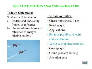
RELATIVE MOTION ANALYSIS: VELOCITY (Section 16.5) • Today’s Objectives: • Students will be able to: • Describe the velocity of a rigid body in terms of translation and rotation components. • Perform a relative-motion velocity analysis of a point on the body. In-Class Activities: • Check homework, if any • Reading quiz • Applications • Translation and rotation components of velocity • Relative velocity analysis • Concept quiz • Group problem solving • Attention quiz
APPLICATIONS As the slider block A moves horizontally to the left with vA, it causes the link CB to rotate counterclockwise. Thus vB is directed tangent to its circular path. Which link is undergoing general plane motion? How can its angular velocity, , be found?
APPLICATIONS (continued) Planetary gear systems are used in many automobile automatic transmissions. By locking or releasing different gears, this system can operate the car at different speeds. How can we relate the angular velocities of the various gears in the system?
= Disp. due to translation drB=drA+drB/A Disp. due to rotation Disp. due to translation and rotation RELATIVE MOTION ANALYSIS: DISPLACEMENT When a body is subjected to general plane motion, it undergoes a combination of translation and rotation. Point A is called the base point in this analysis. It generally has a known motion. The x’-y’ frame translates with the body, but does not rotate. The displacement of point B can be written:
= + RELATIVE MOTION ANALYSIS: VELOCITY The velocity at B is given as :(drB/dt) = (drA/dt) + (drB/A/dt)or vB=vA+vB/A Since the body is taken as rotating about A, vB/A = drB/A/dt = w x rB/A Here w will only have a k component since the axis of rotation is perpendicular to the plane of translation.
RELATIVE MOTION ANALYSIS: VELOCITY (continued) vB = vA + w x rB/A When using the relative velocity equation, points A and B should generally be points on the body with a known motion. Often these points are pin connections in linkages. Here both points A and B have circular motion since the disk and link BC move in circular paths. The directions of vA and vB are known since they are always tangent to the circular path of motion.
RELATIVE MOTION ANALYSIS: VELOCITY (continued) vB = vA + w x rB/A When a wheel rolls without slipping, point A is often selected to be at the point of contact with the ground. Since there is no slipping, point A has zero velocity. Furthermore, point B at the center of the wheel moves along a horizontal path. Thus, vB has a known direction, e.g., parallel to the surface.
PROCEDURE FOR ANALYSIS The relative velocity equation can be applied using either a Cartesian vector analysis or by writing scalar x and y component equations directly. Scalar Analysis: 1. Establish the fixed x-y coordinate directions and draw a kinematic diagram for the body. Then establish the magnitude and direction of the relative velocity vector vB/A. 2. Write the equation vB = vA + vB/A and by using the kinematic diagram, underneath each term represent the vectors graphically by showing their magnitudes and directions. 3. Write the scalar equations from the x and y components of these graphical representations of the vectors. Solve for the unknowns.
PROCEDURE FOR ANALYSIS (continued) Vector Analysis: 1. Establish the fixed x-y coordinate directions and draw the kinematic diagram of the body, showing the vectors vA, vB, rB/A and w. If the magnitudes are unknown, the sense of direction may be assumed. 2. Express the vectors in Cartesian vector form and substitute into vB = vA + w x rB/A. Evaluate the cross product and equate respective i and j components to obtain two scalar equations. 3. If the solution yields a negative answer, the sense of direction of the vector is opposite to that assumed.
EXAMPLE 1 Given: Block A is moving down at 2 m/s. Find: The velocity of B at the instant = 45. Plan: 1. Establish the fixed x-y directions and draw a kinematic diagram. 2. Express each of the velocity vectors in terms of their i, j, k components and solve vB = vA + w x rB/A.
EXAMPLE 1 (continued) Solution: vB = vA + wAB x rB/A vBi= -2 j + (wkx (0.2 sin 45 i - 0.2 cos 45 j )) vBi= -2 j + 0.2 w sin 45 j + 0.2 w cos 45 i Equating the i and j components gives: vB = 0.2 w cos 45 0 = -2 + 0.2 w sin 45 Solving: w = 14.1 rad/s or wAB= 14.1 rad/s k vB = 2 m/s or vB = 2 m/s i
EXAMPLE 2 Given:Collar C is moving downward with a velocity of 2 m/s. Find: The angular velocities of CB and AB at this instant. Plan: Notice that the downward motion of C causes B to move to the right. Also, CB and AB both rotate counterclockwise. First, draw a kinematic diagram of link CB and use vB = vC + wCB x rB/C. (Why do CB first?) Then do a similar process for link AB.
EXAMPLE 2 (continued) Solution: Link CB. Write the relative-velocity equation: vB = vC + wCB x rB/C vBi= -2 j + wCB k x (0.2 i - 0.2 j ) vBi = -2 j + 0.2wCB j + 0.2 wCB i By comparing the i, j components: i: vB = 0.2 wCB => vB = 2 m/s i j: 0 = -2 + 0.2 wCB => wCB = 10 rad/s k
y x EXAMPLE 2 (continued) Link AB experiences only rotation about A. Since vBis known, there is only one equation with one unknown to be found. vB = wAB x rB/A 2 i = wAB k x (-0.2 j ) 2 i = 0.2 wAB i By comparing the i-components: 2 = 0.2 wAB So, wAB = 10 rad/s k
GROUP PROBLEM SOLVING Given: The crankshaft AB is rotating at 500 rad/s about a fixed axis passing through A. Find: The speed of the piston P at the instant it is in the position shown. Plan: 1) 2)
GROUP PROBLEM SOLVING (continued) Solution: 1) First draw the kinematic diagram of link AB. Applying the relative velocity equation vB = -50 j m/s
GROUP PROBLEM SOLVING (continued) 2) Now consider link BC. Applying the relative velocity equation: vC = -50 j m/s
INSTANTANEOUS CENTER (IC) OF ZERO VELOCITY (Section 16.6) Today’s Objectives: Students will be able to: a) Locate the instantaneous center (IC) of zero velocity. b) Use the IC to determine the velocity of any point on a rigid body in general plane motion. In-Class Activities: • Check homework, if any • Reading quiz • Applications • Location of the IC • Velocity analysis • Concept quiz • Group problem solving • Attention quiz
APPLICATIONS The instantaneous center of zero velocity for this bicycle wheel is at the point in contact with ground. The velocity direction at any point on the rim is perpendicular to the line connecting the point to the IC. Which point on the wheel has the maximum velocity?
APPLICATIONS (continued) As the board slides down the wall (to the left) it is subjected to general plane motion (both translation and rotation). Since the directions of the velocities of ends A and B are known, the IC is located as shown. What is the direction of the velocity of the center of gravity of the board?
INSTANTANEOUS CENTER OF ZERO VELOCITY For any body undergoing planar motion, there always exists a point in the plane of motion at which the velocity is instantaneously zero (if it were rigidly connected to the body). This point is called the instantaneous center of zero velocity, or IC. It may or may not lie on the body! If the location of this point can be determined, the velocity analysis can be simplified because the body appears to rotate about this point at that instant.
LOCATION OF THE INSTANTANEOUS CENTER To locate the IC, we can use the fact that the velocity of a point on a body is always perpendicular to the relative position vector from the IC to the point. Several possibilities exist. First, consider the case when velocity vA of a point A on the body and the angular velocity w of the body are known. In this case, the IC is located along the line drawn perpendicular to vA at A, a distance rA/IC = vA/w from A. Note that the IC lies up and to the right of A since vA must cause a clockwise angular velocity w about the IC.
LOCATION OF THE INSTANTANEOUS CENTER (continued) A second case is whenthe lines of action of two non-parallel velocities, vA and vB,are known. First, construct line segments from A and B perpendicular to vA and vB. The point of intersection of these two line segments locates the IC of the body.
LOCATION OF THE INSTANTANEOUS CENTER (continued) A third case is when the magnitude and direction of two parallel velocities at A and B are known. Here the location of the IC is determined by proportional triangles. As a special case, note that if the body is translating only (vA = vB), then the IC would be located at infinity. Then w equals zero, as expected.
VELOCITY ANALYSIS The velocity of any point on a body undergoing general plane motion can be determined easily once the instantaneous center of zero velocity of the body is located. Since the body seems to rotate about the IC at any instant, as shown in this kinematic diagram, the magnitude of velocity of any arbitrary point is v = w r, where r is the radial distance from the IC to the point. The velocity’s line of action is perpendicular to its associated radial line. Note the velocity has a sense of direction which tends to move the point in a manner consistent with the angular rotation direction.
EXAMPLE 1 Given: A linkage undergoing motion as shown. The velocity of the block, vD, is 3 m/s. Find: The angular velocities of links AB and BD. Plan: Locate the instantaneous center of zero velocity of link BD. Solution: Since D moves to the right, it causes link AB to rotate clockwise about point A. The instantaneous center of velocity for BD is located at the intersection of the line segments drawn perpendicular to vB and vD. Note that vB is perpendicular to link AB. Therefore we can see that the IC is located along the extension of link AB.
Since the magnitude of vD is known, the angular velocity of link BD can be found from vD = wBD rD/IC . wBD = vD/rD/IC = 3/0.566 = 5.3 rad/s Link AB is subjected to rotation about A. wAB = vB/rB/A = (rB/IC)wBD/rB/A = 0.4(5.3)/0.4 = 5.3 rad/s EXAMPLE 1 (continued) Using these facts, rB/IC = 0.4 tan 45° = 0.4 m rD/IC = 0.4/cos 45° = 0.566 m
Given:The disk rolls without slipping between two moving plates. vB = 2v vA = v EXAMPLE 2 Find: The angular velocity of the disk. Plan:This is an example of the third case discussed in the lecture notes.Locate the IC of the disk using geometry and trigonometry. Then calculate the angular velocity.
v A x IC w O r B 2v EXAMPLE 2 (continued) Solution: Using similar triangles: x/v = (2r-x)/(2v) or x = (2/3)r Therefore w = v/x = 1.5(v/r)
GROUP PROBLEM SOLVING Given: The four bar linkage is moving with wCD equal to 6 rad/s CCW. Find: The velocity of point E on link BC and angular velocity of link AB. Plan:
GROUP PROBLEM SOLVING (continued) Link CD: Link AB: Link BC: wBC = 10.39 rad/s
vE = 4.76 m/s where q = tan-1(0.3/0.346) = 40.9° q GROUP PROBLEM SOLVING (continued) wAB = 6 rad/s
RELATIVE MOTION ANALYSIS: ACCELERATION (Section 16.7) Today’s Objectives: Students will be able to: a) Resolve the acceleration of a point on a body into components of translation and rotation. b) Determine the acceleration of a point on a body by using a relative acceleration analysis. In-Class Activities: • Check homework, if any • Reading quiz • Applications • Translation and rotation components of acceleration • Relative acceleration analysis • Roll-without-slip motion • Concept quiz • Group problem solving • Attention quiz
APPLICATIONS In the mechanism for a window, link AC rotates about a fixed axis through C, while point B slides in a straight track. The components of acceleration of these points can be inferred since their motions are known. To prevent damage to the window, the accelerations of the links must be limited. How can we determine the accelerations of the links in the mechanism?
= + dv dv dv / B A B A dt dt dt These are absolute accelerations of points A and B. They are measured from a set of fixed x,y axes. This term is the acceleration of B with respect to A. It will develop tangential and normal components. RELATIVE MOTION ANALYSIS: ACCELERATION The equation relating the accelerations of two points on the body is determined by differentiating the velocity equation with respect to time. The result is aB=aA+ (aB/A)t+(aB/A)n
Graphically: aB = aA+ (aB/A)t+(aB/A)n = + RELATIVE MOTION ANALYSIS: ACCELERATION The relative tangential acceleration component (aB/A)t is (xrB/A) and perpendicular torB/A. The relative normal acceleration component (aB/A)n is (-2rB/A) and the direction is always from B towards A.
RELATIVE MOTION ANALYSIS: ACCELERATION (continued) Since the relative acceleration components can be expressed as (aB/A)t =rB/Aand (aB/A)n = - 2rB/A the relative acceleration equation becomes aB=aA+rB/A- 2rB/A Note that the last term in the relative acceleration equation is not a cross product. It is the product of a scalar (square of the magnitude of angular velocity, w2) and the relative position vector, rB/A.
APPLICATION OF RELATIVE ACCELERATION EQUATION In applying the relative acceleration equation, the two points used in the analysis (A and B) should generally be selected as points which have a known motion, such as pin connections with other bodies. In this mechanism, point B is known to travel along a circular path, so aB can be expressed in terms of its normal and tangential components. Note that point B on link BC will have the same acceleration as point B on link AB. Point C, connecting link BC and the piston, moves along a straight-line path. Hence, aC is directed horizontally.
PROCEDURE FOR ANALYSIS: RELATIVE ACCELERATION ANALYSIS 1. Establish a fixed coordinate system. 2. Draw the kinematic diagram of the body. 3. Indicate on it aA, aB, , , and rB/A. If the points A and B move along curved paths, then their accelerations should be indicated in terms of their tangential and normal components, i.e., aA= (aA)t + (aA)n and aB = (aB)t + (aB)n. 4. Apply the relative acceleration equation: aB=aA+rB/A- 2rB/A 5. If the solution yields a negative answer for an unknown magnitude, it indicates the sense of direction of the vector is opposite to that shown on the diagram.
EXAMPLE 1 Given: Point A on rod AB has an acceleration of 3 m/s2 and a velocity of 2 m/s at the instant the rod becomes horizontal. Find: The angular acceleration of the rod at this instant. Plan: Follow the problem solving procedure! Solution: First, we need to find the angular velocity of the rod at this instant. Locating the instant center (IC) for rod AB (which lies above the midpoint of the rod), we can determine : wA = vA/rA/IC = vA/(5/cos 45) = 0.283 rad/s
EXAMPLE 1 (continued) Since points A and B both move along straight-line paths, aA= 3 (cos 45 i - sin 45 j) m/s aB = aB(cos 45 i + sin 45 j) m/s Applying the relative acceleration equation aB = aA + a x rB/A – w2rB/A (aB cos 45 i + aB sin 45 j = (3 cos 45 i – 3 sin 45 j) + (ak x 10 i) – (0.283)2(10i)