Download

1 / 227
2.32k likes | 2.7k Vues
System Design Fundamentals January 2011. Dr. Abdul Razzaq Touqan. System Design Fundamentals. Objectives : -to introduce the building construction determinant -to analyze different systems by finite element method and analogical methods

E N D
System Design FundamentalsJanuary 2011 Dr. Abdul Razzaq Touqan
System Design Fundamentals Objectives: -to introduce the building construction determinant -to analyze different systems by finite element method and analogical methods -to build conceptual abilities in designing reinforced concrete elements.
Preface • Most of the education and research is concentrated in analytical skills and very little in creativity skills (analogical skills) which is fundamental in design. • Creativity is the ability to conceive, generate design alternatives and preserve environment. It requires compositional ability. • Compositional ability requires conceptual understanding which is based on both: “a feeling” for behavior and “approximate” analysis\design skills
Preface • System design addresses the need for conceptual design skills. • A design project provides opportunity for teams of students to create conceptual designs and make representations to a design “jury”. • It provides opportunity to concentrate on the structure as a whole and very little on the element behaviour.
Chapter 1 Introduction • Introduction to systems • Purpose • System determinants • Example 1 • Standards versus codes • Problem set #1 (due ) • Fundamentals of thinking
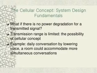
Introduction to systems: • A system is a necessary part of life. It occurs at any level, ranging from the molecular structure of material to laws of universe. • As order, it relates all the parts of a whole reflecting some pattern of organization. • Everything has system, even if we have not yet recognized it. Societies are a form of structural systems to properly function- language has system, the interrelationship of plants and animals with their environment represents equilibrium in nature which is a system by itself.
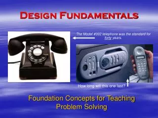
Purpose • The purpose of a system is to combine global understanding with local details. • Discuss face of human being and how systematically it combines architectural, structural, mechanical and electrical systems
System determinants: Engineering systems must develop: • Support system (structure\science): • It holds the structure up so that it does not collapse. A need for strength to achieve this. • It prevents elements to deform or crack excessively. A need for serviceability to achieve this. • It makes the structure withstands severe events (like earthquakes, wind storms, …). A special design is needed to achieve this (savings in materials: smaller sections + larger strength).
System determinants • Faith system (facts/fashion): It Defines • space configuration based on functional needs (social, economical), • The capacity of adaptation based on freedom needs (legal, environmental) • geometrical shape based on form needs (culture, esthetics)
Example #1 • A client likes to build a carage for his car. If the car dimensions are 5mX2mX1.5m height. Select a value for the dimensions shown and defend your selection in no more than 20 words: (note: a family of acceptable design solutions can be done as long as they achieve system determinants)
Standards versus codes • Minimum standards are controlled by design (ethic) codes. • Design codes are based on model codes which often specify a particular industry standard. • Municipal and state governments adopt the model codes (or develop their own codes) and thus provide legally enforceable laws with which the engineer must comply. • The intent of the code is not to limit engineering creativity, but to provide minimum standards to safeguard the health and safety of the public.
Problem set #1 (Project: due ) • Plan of a land and permitted building area is shown next with municipality main water line and manhole for waste water disposal. The allowable bearing capacity of the soil is 0.4MPa • The design determinants for a preliminary study are:
Problem set #1 continued • Prepare a draft first floor plan for parking. • Prepare a draft plan to serve two residential apartments in each floor (3.12m elevation) and specify number of stories allowed according to your local code. • Prepare a draft mechanical and electrical plan for first floor and show on it connections from the building to municipality lines. • Defend your ideas in no more than 150 words and in points. • You must work in groups of 5 each, each group must select one choice of a and b as provided next page with the help of the instructor.
Fundamentals of thinking: Input • Start with present worked examples (get advantage of other thoughts-how Japan builds up quickly). • See (a good engineer is a good observer), • Read (plans of others), • Ask (learn how to gather hidden information making sure you are satisfied with the answer, if not then argue but be careful not to go more than one round for each point (learn how to express yourself in words))
Fundamentals of thinking: Input and Processing • Try to solve the problem by: • Study your subject first of all. • Get an overview about all tasks needed for solution. • Select members of your team based on qualifications: capability to do the work + commitment. Choose a qualified team leader. • Divide the tasks between the team members. • Put a study plan (allocate time for each task + plan alternatives). • Think how to do your part of the work on paper (learn how to express yourself in writing).
Fundamentals of thinking: Processing and Output • Systematical management of tasks • Survey literature of the subject (system determinants). Be careful to cover all sides of the problem. • Put a plan how to cover general principles before particular ones • Make sure to stress the important issues and basic principles (support your work by scientific proof) Put contents of your final report • Unify with your team members all symbols, wording, software …etc to be used to present the final report. • Perform your study plan and see how well it is. • Get feed back from all your team members about the whole project to decide to continue or go to alternatives
End of chapter 1 Let Learning Continue
Chapter 2 Design methodology • Limit States Design • Strength Limit State • Serviceability Limit State • Special Limit State • Limit States Design • Design Philosophy • Strength Design Method • Safety Provisions • Variability in Resistance • Variability in Loading • Consequences of Failure • Margin of Safety
Limit State Design Limit State: Condition in which a structure or structural element is no longer acceptable for its intended use. Major groups for RC structural limit states • Strength • Serviceability • Special
Strength Limit State • Structural collapse of all or part of the structure ( very low probability of occurrence) and loss of life can occur (a structure will not fail as long as there is a safe load path to the foundation). Major limit states are: (a) Loss of equilibrium of a part or all of a structure as a rigid body (tipping, sliding of structure…: reaction could not be developed). (b) Rupture of critical components causing partial or complete collapse. (flexural, shear failure…).
Strength Limit States (c) Progressive Collapse • Minor local failure overloads causing adjacent members to fail until entire structure collapses. • Structural integrity is provided by tying the structure together with correct detailing of reinforcement which provides alternative load paths to prevent localized failure.
Serviceability Limit State • Functional use of structure is disrupted, but collapse is not expected. More often tolerated than a strength limit state since less danger of loss of life. Major limit states are: (a) Excessive crack width leads to leakage which causes corrosion of reinforcement resulting in gradual deterioration of structure. (b) Excessive deflections for normal service • malfunction of machinery • visually unacceptable • damage of nonstructural elements • changes in force distributions (no compatibility) • ponding on roofs leading to collapse of roof
Serviceability Limit State (c ) Undesirable vibrations • Vertical: floors/ bridges • Lateral\torsional: tall buildings
Special Limit State Damage/failure caused by abnormal conditions or loading. These could be due to: (a) Extreme earthquakes: damage/collapse (b) Floods: damage/collapse (c) Effects of fire, explosions, or vehicular collisions. (d) Effects of corrosion, deterioration (e) Long-term physical or chemical instability
Limit States Design • Identify all potential modes of failure. • Determine acceptable safety levels for normal structures building codes load combination factors.
Limit States Design • Consider the significant limit states. • Members are designed for strength limit states • Serviceability is checked. Exceptions may include • water tanks (crack width) • monorails (deflection) • Noise in auditoriums
Design Philosophy Two philosophies of design have long prevalent. (a)Working stress method focusing on conditions at service loads. (b)Strength design method focusing on conditions at loads greater than the service loads when failure may be imminent. The strength design method is deemed conceptually more realistic to establish structural safety.
Strength Design Method In the strength method, the service loads are increased sufficiently by factors to obtain the load at which failure is considered to be “imminent”. This load is called the factored load or factored service load.
Strength Design Method Strength provided is computed in accordance with rules and assumptions of behavior prescribed by the building code and the strength required is obtained by performing a structural analysis using factored loads. The “strength provided” has commonly referred to (wrongly) as “ultimate strength”. However, it is a code defined value for strength and not necessarily “ultimate”. The ACI Code uses a conservative definition of strength.
Safety Provisions Structures and structural members must always be designed to carry some reserve load above what is expected under normal use. There are three main reasons why some sort of safety factor are necessary in structural design. [1] Variability in resistance. [2] Variability in loading. [3] Consequences of failure.
Variability in Resistance: R • Variability of the strengths of concrete and reinforcement. • Differences between the as-built dimensions and those found in structural drawings. • Effects of simplification made in the derivation of the members resistance (i.e. simplifying assumptions).
Variability in Resistance: R Comparison of measured and computed failure moments based on all data for reinforced concrete beams with fc > 14MPa The variability shown is due largely to simplifying assumptions.
Variability in sustained Loads: S Frequency distribution of sustained component of live loads in offices. In small areas: Average=0.65kN/m2 1% exceeded=2.2kN/m2 Codeuse 2.5kN/m2 In large areas: average almost the same, but variability decreases. (notice that large areas can be used for parties, temporary storage…etc, thus larger LL is needed)
Consequences of Failure A number of subjective factors must be considered in determining an acceptable level of safety. • Potential loss of life: larger SF for auditorium than a storage building. • Cost of clearing the debris and replacement of the structure and its contents. • Cost to society: collapse of a major road. • Type of failure, warning of failure, existence of alternative load paths.
Margin of Safety The term Y = R - S is called the safety margin. The probability of failure is defined as: and the safety index is
Problem set #2 Due ( ) • Types of design can be classified as: • Creative • Development • Copy • Analyze previous types showing advantages and disadvantages of each type in view of what you learned from previous two chapters.
End of chapter 2 Let Learning Continue
Chapter 3 Loadings • Loading Specifications • Dead Loads • Live Loads • Environmental Loads • Classification of Buildings for Wind, Snow and Earthquake Loads • Snow Loads • Earthquake Loads • Roof Loads • Construction Loads • Load factors
Building Codes Cities in the U.S. generally base their building code on one of the three model codes: • Uniform Building Code • Basic Building Code (BOCA) • Standard Building Code These codes have been consolidated in the 2000 International Building Code.
Loading Specifications Loadings in these codes are mainly based on ASCE Minimum Design Loads for Buildings and Other Structures ASCE 7-05.
Dead Loads • Weight of all permanent construction • Constant magnitude and fixed location Examples: • Weight of the Structure (Walls, Floors, Roofs, Ceilings, Stairways) • Fixed Service Equipment (HVAC, Piping Weights, Cable Tray, etc.
Live Loads • Loads produced by use and occupancy of the structure. • Maximum loads likely to be produced by the intended use. • Not less than the minimum uniformly distributed load given by Code.
Live Loads See Table 4-1 from ASCE 7-05 Stairs and exitways: 4.8KN/m2. Storage warehouses: 6KN/m2 (light) 12 KN/m2 (heavy) Minimum concentrated loads are also given in the codes.
Live Loads ASCE 7-05 allows reduced live loads for members with influence area (KLLAT) of 38m2 or more (not applied for roof): where L 0.50 Lo for members supporting one floor 0.40 Lo otherwise KLL =live load element factor (Table 4.2) =2 for beams =4 for columns
Environmental Loads • Snow Loads • Earthquake • Wind • Soil Pressure • Roof Loads • Temperature Differentials • …etc
Classification of Buildings for Wind, Snow and Earthquake Loads Based on Use Categories (I through IV) I II Buildings and other structures that represent a low hazard to human life in the event of a failure (such as agricultural facilities), I=1 Buildings/structures not in categories I, III, and IV, I=1