Download
1 / 58
580 likes | 668 Vues
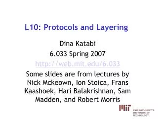
CS551: Layering and Addressing. Christos Papadopoulos ( http://netweb.usc.edu/cs551/). Protocols. Set of rules governing communication between network elements (applications, hosts, routers) Protocols define: Format and order of messages Actions taken on receipt of a message

E N D
CS551:Layering and Addressing Christos Papadopoulos (http://netweb.usc.edu/cs551/)
Protocols • Set of rules governing communication between network elements (applications, hosts, routers) • Protocols define: • Format and order of messages • Actions taken on receipt of a message • Protocols are hard to design • We need design guidelines!
Layering Teleconferencing User A User B Peers Application Transport Network Link Host Host Layering: technique to simplify complex systems
Layering Characteristics • Each layer relies on services from layer below and exports services to layer above • Interface defines interaction • Hides implementation - layers can change without disturbing other layers (black box)
OSI Model: 7 Protocol Layers • Physical: how to transmit bits • Data link: how to transmit frames • Network: how to route packets hop2hop • Transport: how to send packets end2end • Session: how to tie flows together • Presentation: byte ordering, security • Application: everything else!
Layering General Issues • Reliability • Flow control • Fragmentation • Multiplexing • Connection setup (handshaking) • Addressing/naming (locating peers)
Example: Transport Layer • First end-to-end layer • End-to-end state • May provide reliability, flow and congestion control
Example: Network Layer • Point-to-point communication • Network and host addressing • Routing
Is Layering Harmful? • Sometimes.. • Layer N may duplicate lower level functionality (e.g., error recovery). • Layers may need same info (timestamp, MTU). • Strict adherence to layering may hurt performance. • Naïve layer implementation frequently hurts performance.
Course Focus IP and TCP
IP Application Transport Network Link Host Router Router Host
IP Functions • Type of service • Not used until recently • Identification, flags and fragment offset • Fragmentation • Time to live • Bounded delivery • Protocol • (De)multiplexing higher layer protocols
Other Fields • Length • IP packet length limited to 64K • Header checksum • Ensures some degree of header integrity
Fragmentation • Forwarding costs per packet • Nice if we can send large chunks of data • Different link-layers have different MTUs • Fragmentation • Intra-network • Inter-network
Fragmentation Is Harmful • Uses resources poorly • Example of packet just bigger than MTU • Poor end-to-end performance • Loss of a fragment • Reassembly is hard • Buffering constraints
Path MTU Discovery • Hosts dynamically discover MTU of path • Send message with don’t fragment bit • Get ICMP message indicating size • What happens if path changes? • Increasing/decreasing path MTU • Usually implemented by the transport layer • Expected that future routing protocols will provide MTU information
Path MTU • Algorithm: • Initialize MTU to MTU to next hop • Send datagrams with DF bit set • If “datagram too big”, decrease MTU • Periodically (>5mins, or >1min after previous increase), increase MTU • Some routers will return proper MTU • MTU values cached in routing table
Addressing in IP • IP addresses are names of interfaces • DNS names are names of hosts • DNS binds host names to interfaces • Routing binds interface names to paths
Addressing Considerations • Fixed length or variable length? • Issues: • Flexibility • Processing costs • Header size • Engineering choice: IP uses fixed length addresses
Addressing Considerations • Structured vs flat • Issues • Need structure for designing scalable binding from interface name to route! • How many levels? Fixed? Variable?
Packet Traveling Through the Internet Routers send packet to next closest hop H R H R H H R R R R R H R H: Hosts R: Routers H
IP Addressing Hierarchy Backbones Regionals Campus LANs
Some Special IP Addresses • 127.0.0.1: local host (a.k.a. The loopback address. • 127.X.X.X: same as above. • Host bits all set to 0: network address. • Host bits all set to 1: broadcast address. • 0.0.0.0: this host on this network.
IP Addresses • Fixed length: 32 bits • Initial classful structure
Class Sizes Total IP address size: 4 billion • Class A: 128 networks, 16M hosts • Class B: 16K networks, 64K hosts • Class C: 2M networks, 256 hosts
IP Address Classes(Some Are Obsolete) Network ID Host ID 8 16 24 32 Class A Network ID 0 Host ID Class B 10 Class C 110 Class D Multicast Addresses 1110 Class E 1111 Reserved for experiments
Network Subnet Host Subnet Addressing • Very few LANs have close to 64K hosts • for networks with more than 255 hosts • Variable length subnet masks • could subnet a class B into several chunks
Subnetting • Simple and elegant way to reduce the total number of network addresses that are assigned. network host network subnet host 1111.. ..1111 00000000 mask
Subnetting Example • Assume an organization was assigned address 150.100 • Assume < 100 hosts per subnet • How many host bits do we need? • seven • What is the network mask? • 11111111 11111111 11111111 10000000 • 255.255.255.128
Using Subnet Mask • Assume a packet arrives with address 150.100.12.176 • Step 1: AND address with subnet mask • (150.100.12.176) AND (255.255.255.128) • result: 150.100.12.128 which is the target network • Target network has hosts in the range • 150.100.12.129 - 150.100.12.254
150.100.12.154 150.100.12.176 H1 H2 150.100.12.128 150.100.12.129 150.100.12.24 150.100.12.55 150.100.0.1 R1 H3 H4 To Internet 150.100.12.4 150.100.12.0 150.100.12.1 150.100.15.11 R2 H5 150.100.15.54 150.100.15.0 Subnet Addressing Example
150.100.12.154 150.100.12.176 H1 H2 150.100.12.128 150.100.12.129 150.100.12.24 150.100.12.55 150.100.0.1 R1 H3 H4 To Internet 150.100.12.4 150.100.12.0 150.100.12.1 150.100.15.11 R2 H5 150.100.15.54 150.100.15.0 Routing to the Network A packet destined to 150.100.15.11 arrives R1 applies a 9-bit subnet mask and gets the address 150.100.15.0 R1 looks up its routing table and sends the packet to R2
150.100.12.154 150.100.12.176 H1 H2 Destination Next hop Flags Interface 150.100.12.128 150.100.12.129 H lo0 150.100.12.24 150.100.12.55 127.0.0.1 127.0.0.1 150.100.0.1 R1 H3 H4 Routing table at H5 default 150.100.15.54 G emd0 To Internet 150.100.12.4 150.100.15.0 150.100.15.11 emd0 150.100.12.0 150.100.12.1 150.100.15.11 R2 H5 150.100.15.54 150.100.15.0 Routing Within the Subnet H5 wants to send pkt to H2. • Lookup rules: • exact match • network match • default route Search for longest matching prefix
150.100.12.154 150.100.12.176 H1 H2 150.100.12.128 150.100.12.129 150.100.12.24 150.100.12.55 150.100.0.1 R1 H3 H4 Routing table at R2 To Internet 150.100.12.4 Destination Next hop Flags Interface 150.100.12.0 150.100.12.1 150.100.15.11 H lo0 R2 H5 127.0.0.1 127.0.0.1 150.100.15.54 default 150.100.12.4 G emd0 150.100.15.0 150.100.15.0 150.100.15.11 emd1 emd1 150.100.12.0 150.100.12.1 Routing Within the Subnet From H5, Packet reaches R2. R2 delivers the packet to R1.
150.100.12.154 150.100.12.176 H1 H2 150.100.12.128 150.100.12.129 150.100.12.24 150.100.12.55 150.100.0.1 R1 H3 H4 To Internet 150.100.12.4 150.100.12.0 150.100.12.1 150.100.15.11 R2 H5 150.100.15.54 150.100.15.0 Routing Within the Subnet R1 has direct route and delivers packet to H2. Routing table at R1 Destination Next hop Flags Interface H lo0 127.0.0.1 127.0.0.1 150.100.12.176 150.100.12.176 emd0 150.100.12.0 150.100.12.4 emd1 G emd1 150.100.15.0 150.100.12.1
IP Address Problem (1991)? • Address space depletion • in danger of running out of classes A and B • Routing table explosion
Some Problems • Class B sparsely populated • but people refuse to give it back • One solution: assign class C addresses • how do you allocate to avoid routing table explosion? • Addresses not geographically related • addresses given by your ISP • blocks assigned to various countries
Classless Inter-domain Routing (CIDR) • Do not use classes to determine network ID • Use common part of address as network number • i.e., use netmask (/xx bits) for network address • E.g., addresses 192.4.16 - 196.4.31 have the first 20 bits in common. Thus, we use this as the network number • netmask is /20 • In CIDR /xx is valid for almost any xx
CIDR Addressing • A block of addresses is described by • address prefix • mask • Examples: • 10/8 denotes addresses from 10.0.0.0 to 10.255.255.255 • /xx indicates number of significant bits
Classless Inter-Domain Routing (CIDR) • Several key ideas • allocate addresses to organizations in power-of-two blocks • organizations get addresses from provider’s block • provider aggregates • Addresses: • address utilization • routing table size
Old classes and CIDR • Class A network is a /8 • Class B network is a /16 • Class C network is a /24
CIDR prefixes CIDR Blk Prfx # Eqiv Class C # of Hosts /28 1/16 16 /27 1/8 32 /26 1/4 64 /25 1/2 128 /24 1 class C 256 /23 2 512 /22 4 1,024 /21 8 2,048 /20 16 4,096 /19 32 8,192 /18 64 16,384 /17 128 32,768 /16 256=1 class B 65,536 /15 512 131,072 /14 1,024 262,144 /13 2,048 524,288
CIDR example • Network admin is allocated 8 class C chunks, 201.10.0.0 to 201.10.7.255 • Allocation uses 3 bits of class C space • Remaining 21 bits are network number, written as 201.10.0.0/21 • 21 is prefix indication which must be carried with address • Routing protocols carry this prefix
CIDR Illustration 12/6 Provider 12/8 13/8 15/8 14/8
explanation • 12/6 = 0000 1100.0.0.0 • 12/8 = 0000 1100.0.0.0 • 13/8 = 0000 1101.0.0.0 • 14/8 = 0000 1110.0.0.0 • 15/8 = 0000 1111.0.0.0
CIDR Shortcomings • Multi-homing • Customer selecting a new provider • Some other ideas • geographic addressing • Is it enough? Do we need a new IP?
Network Address Translation (NAT) • Kludge (but useful) • Sits between your network and the Internet • Translates local network layer addresses to global IP addresses • Has a pool of global IP addresses (less than number of hosts on your network)
Dg Sp Dg Sg data data NAT Illustration Pool of global IP addresses Internet G P D Private network NAT • Operation:Sp wants to talk to Dg: • Create Sg-Sp mapping • Replace Sp with Sg for outgoing packets • Replace Sg with Sp for incoming packets