Ladder Testing at IPHC and LBL
90 likes | 253 Vues
Ladder Testing at IPHC and LBL. Outline. Synchronization of the ladder Ladder L1 operated in SYNC Ladder L2 (LBL) no SYNC Sensor with a faulty output Summary. Synchronization of the ladder. As suggested by Gilles. Sync sequence: Stop the main CLK RSTB JTAG configuration

Ladder Testing at IPHC and LBL
E N D
Presentation Transcript
Outline • Synchronization of the ladder • Ladder L1 operated in SYNC • Ladder L2 (LBL) no SYNC • Sensor with a faulty output • Summary
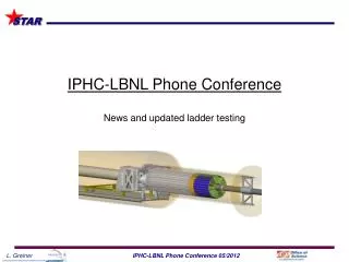
Synchronization of the ladder As suggested by Gilles • Sync sequence: • Stop the main CLK • RSTB • JTAG configuration • Enable the main CLK • START • Enable/disable CLK by using synchronous OE in the PLL device (CY7B9950) • A relatively small patch in the existing hardware • A small modification in the new MTB board design OE Ladder CLK
L1 – “full” decoupling + SYNC • A small mystery • Single sensor – very noisy ? • One of ten – OK
Normal readout mode (20 RSTB x 5 START) Stable readout Same cut settings for LOW and HIGH threshold operation Clearly, two different operating points Chip 1 – HIGH Chip 1 – LOW Chip 2 – HIGH Chip 2 – LOW Chip 6 – HIGH Chip 6 – LOW
L2 – tested at LBL (“full” decoupling, no sync) Fit problems Good repeatability – tested x10 for each sensor, but… issues in the normal readout mode
Sensor with a faulty output • L1 chip 4MTB output 5.2 - green MTB output 5.1 - red • Output delay: • @160 MHz Tx=40 7.4 ns • @160 MHz Tx=100 3.3 ns • @ 50 MHz Tx=40 7.2 ns • @ 50 MHz Tx>100 3.0 ns • @ 50 MHz Tx=20 12.6 ns patt mode, no cnt, header FFFF, trailer EEEE, TX=40 AAFF, TX=40 AAFF, TX=100 AAFF, TX=100, 10 ns/div
Synchronization problem has been solved IPHC solution: stop CLK, RSTB, JTAG, enable CLK, START CLK enable/disable via PLL synchronous OE minor modifications in the PXL hardware Why is it different than in Phase-1 ? L1 (IPHC) Good noise performance with decoupling capacitors and in sync Stable readout in the normal readout mode Small noise degradation @ LOW thresholds L2 (LBL) Similar noise performance to L1 To be tested in SYNC Degraded performance using “sense” regulators – under investigation Summary