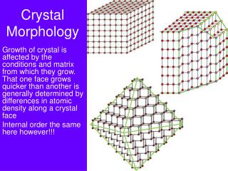
Crystal Morphology
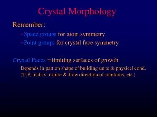
Crystal Morphology. Growth of crystal is affected by the conditions and matrix from which they grow. That one face grows quicker than another is generally determined by differences in atomic density along a crystal face Internal order the same here however!!!. Why did we go through all this?.

Crystal Morphology
E N D
Presentation Transcript
Crystal Morphology Growth of crystal is affected by the conditions and matrix from which they grow. That one face grows quicker than another is generally determined by differences in atomic density along a crystal face Internal order the same here however!!!
Why did we go through all this? • Lattice types and space groups are important in describing the arrangement of atoms in space • These arrangements result in planes of atoms which are spaced at defined intervals, controlled by the mineral structure, which is described by crystallography • They describe possible planes in crystalline structures where ions are aligned. Light and high-energy particles interact with those planes, which yield powerful diagnostic tools!
How does that translate to what we see?? • Internal order creates changes in planar spacings for different atomic arrangements What can we use to ‘see’ these planar spacings??
X-rays • Another part of the electromagnetic spectrum between 100 and 0.2 Å. • Planck’s law: E=hn =hc/l • Where n is frequency, l is wavelength, h is Planck’s constant, and c is the speed of light
X-ray generation • X-rays are generated by striking a target material with an accelerated e- which causes an excitation. When his excitation ‘relaxes’, or goes back down to standard state, an X-ray is emitted • Usually given in terms of the energy levels those e- come from and go to different levels yield X-rays of different energies (all dependent on the material) • K, L, M shells of a material, from that those shells have different transitions and characteristic relaxations (a, b, g) • Cu Ka is the most intense peak and most commonly used (though others are possible and have a different wavelength, which can be useful!)
X-Ray interaction • Scattering – oscillation of incoming X-rays transfer energy to electrons in material, emitting secondary radiation at about the same frequency and energy as the incoming beam • Interaction of X-rays with same material causes some electrons to go into an excited state, which upon relaxation, emits radiation characteristic of the atom it excited basis for XRF, used to identify chemical makeup of materials • As with other interactions with minerals, there can also be reflection and transmission of X-rays (depending on thickness), but we don’t typically use that information.
l Interference • Constructive and destructive interference – wave properties interact to either cancel out or amplify each other. • When 2+ centers are emitting energy at some wavelength, they will interfere with each other Plane view
Experiment • Relationship between light as particles vs. light as waves • Light scattered by mesh - as it travels and interacts, some waves compliment each other while different waves cancel each other
Diffraction • Combine elements of interference with striking the x-ray at an angle to the material • Relationship between wavelength, atomic spacing, and angle of diffraction for 3-D structures derived by von Laue • Bragg’s determined that you could simplify this and treat it as a reflection off of the planes within an atom…
Bragg’s Law • nl=2dsinΘ • Where n is the order of diffraction (always an integer), l is the wavelength of incident radiation, d is the spacing between planes, and Θ is the angle of incidence (or angle of reflection, they are equal)
Diffraction • Relationship between diffraction and wavelength: • The smaller the diffracting object, the greater the angular spacing of the diffraction pattern • i.e. the smaller the separation between planes, the wider the spacing between diffraction lines • What then is diffraction?? • The failure of light to travel in straight lines (much to Newton’s dismay…) • Young’s 2 slit experiment proved light could bend – scattered and affected by constructive and destructive interference • Bright red = constructive; dark = destructive
Bragg’s Law • nl=2dsinΘ • Where n is the order of diffraction (always an integer), l is the wavelength of incident radiation, d is the spacing between planes, and Θ is the angle of incidence (or angle of reflection, they are equal) • Diffraction here is between parallel planes of atoms the space between them (d) determines the angle of diffraction. • Looking at the laser pattern again where is Bragg’s Law ‘satisfied’ and how many orders of diffraction do we see?
Red Laser analogue • We see orders of diffraction resulting from light coming between grid spacing 2, 3, 4, 5, etc., apart. In a mineral, multiple parallel planes yields similar patterns at higher orders of diffraction – theoretically the angle keeps increasing what do we notice about the intensity though?
l These 2 constructively Interfere good signal! Θ Θ d These 2 destructively Interfere bad signal! l Θ Θ d Bragg’s Law • nl=2dsinΘ • Just needs some satisfaction!!