Evolution of Fiber Optics: From Ancient Techniques to Modern Applications
Delve into the history and techniques of fiber optics, from the rudimentary light pipes of ancient glass blowers to the modern applications in telecommunications and optronics. Explore the breakthroughs in total internal reflection, the integration of laser technology, and the importance of numerical aperture in determining fiber efficiency. Discover the tools of the trade, such as HeNe and diode lasers, and learn how to modulate frequencies for optimal performance. Uncover the critical angles, fractional index differences, and real-world applications that make fiber optics an essential component of modern technology.

Evolution of Fiber Optics: From Ancient Techniques to Modern Applications
E N D
Presentation Transcript
Fiber Optics By Matt Bayliss Jerome Carpenter
History and Background • Techniques of Total Internal Reflection first used by Greek and Venetian glass blowers centuries ago. • Rudimentary principle of “light pipes” formed the basis for the first attempts at guiding light through refractive tubes. • John Tyndall, England - 1870 - Demonstrated that light could be conducted along a curved stream of water. • 1920’s & 30’s - Scientists in England, Germany, and U.S. all experiment with using coated mineral fibers to transmit images. Their ideas are not pursued.
Breaking Through • 1951 - A.C.S. van Heel in Holland theorizes the use of glass coated fibers, experiments with plastic coatings. • 1951 - In England, H.H. Hopkins and N.S. Kapany develop basic techniques for fiber alignment and transmit the first undistorted image through a bundle of uncoated glass fibers. • Kapany later coined the term “fiber optics”, and the use of glass-coated glass fibers is evolved to improve efficiency and reduce distortion. • 1961 - Laser and fiber optics fields are first integrated.
Geometry of Total Internal Reflection • From Basic Electromagnetic theory we take Snell’s Law: • no*sin(thetao) = n’*sin(theta’)
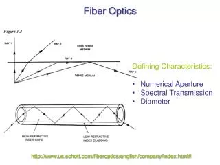
Critical Angle and Numerical Aperture • Define the Critical Angle, C by: sin(C) = n’/no • Snell’s Law + Critical Angle gives us: n*sin(theta) = no*sin(thetao) = no*sin[(pi/2) - C] = no[1-(n’/no)^2]^1/2 • We now define the Numerical Aperture: NA = n*sin(theta) = [no^2-n’^2]^1/2
Fractional Index Difference • For a given fiber, there is a fractional index difference, D = (no - n’)/no • For weakly guiding fibers, D will be <<1, and therefore the critical angle will be large.
Goals • Determine NA • Modulate the laser’s frequency and analyze the output signal
Tools of the trade • HeNe Laser First the chamber is evacuated (high vacuum). Next He and Ne are added. 100% of desired wavelength reflected 99% of desired wavelength is reflected Each photon has an average of 100 passes before it leaves Diode Laser – Same concept, but uses A diode to generate light.
Determining NA • Numerical Aperature – range of angles in which the light is “accepted by the fiber. Actually the sine of the angle at which the fiber only transmits 5% of the original power
Determining NA Rough Determination of Na Better method of determining Na
NA • HeNe Rough estimate = .342 determined to be .375 • NA vs log (power) gave a parabolic curve.
Diode lasers • Differences between the Diode laser and the HeNe laser revisited. • Feed the diode some frequencies • Resistance
Diode Laser and Freq. • Modulation depth fell of exponentially at high frequencies. • Waveform became distorted as frequency increased. • -3dB frequency was 750 Hz
Resistance • 50 ohms –3dB 750 • 10k ohms –3dB ->0
Applications • Telecom • Optronics?