A Power-Efficient High Throughput 32-Thread SPARC Processor
A Power-Efficient High Throughput 32-Thread SPARC Processor. Negar Esmaeilie Falah Instructor : Prof. M. fakhraiee Class Presentation Adopted of ISSCC 2006 / SESSION 5 / PROCESSORS / 5.1. Outline. Motivation Architecture Overview Performance / Power Physical Implementation

A Power-Efficient High Throughput 32-Thread SPARC Processor
E N D
Presentation Transcript
A Power-EfficientHigh Throughput32-Thread SPARC Processor Negar Esmaeilie Falah Instructor : Prof. M. fakhraiee Class Presentation Adopted of ISSCC 2006 / SESSION 5 / PROCESSORS / 5.1
Outline • Motivation • Architecture Overview • Performance / Power • Physical Implementation • Integer Register File • L2 Cache • Conclusion
Motivation • Commercial server applications • High thread level parallelism (TLP) • Low instruction level parallelism (ILP) • Major concerns: • Power • Cooling • Space
The Niagara SPARC Processor • New architecture and new pipeline to achieve throughput and performance/watt • Many small, simple cores • Shallow single issue pipeline • Small L1 caches • Fine-grain multithreading within core • L2 cache shared across all cores • High bandwidth memory sub-system
Architecture Features • CPU with 32 threads to exploit TLP • 8 cores/chip with 4 threads/core to hide memory and pipeline stalls • Shared pipeline to reuse resources • Shared L2 cache for efficient data sharing among threads • High bandwidth memory sub-system to increase throughput: • Highly associative banked L2 cache • High bandwidth crossbar to L2 cache • High bandwidth to DRAM
Floating Point Unit DRAM Control DDR2 144@400 MT/s Sparc 0 L2 Bank 0 Channel 0 Sparc 1 DDR2 144@400 MT/s Sparc 2 L2 Bank 1 Channel 1 Sparc 3 Crossbar DDR2 144@400 MT/s Sparc 4 L2 Bank 2 Channel 2 Sparc 5 DDR2 144@400 MT/s Sparc 6 L2 Bank 3 Channel 3 Sparc 7 Control Register Interface Clock & Test Unit JTAG JBUS System Interface JBUS (200 MHz) SSI ROM Interface SSI (50 MHz) Processor Block Diagram [1]
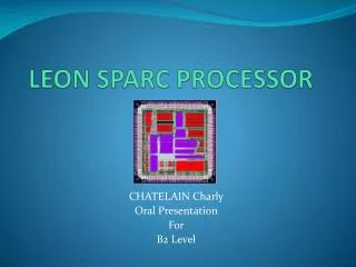
SPARC Core 0 SPARC Core 2 SPARC Core4 SPARC Core 6 L2 Data Bank 0 L2 Data Bank 2 DDR2_0 DDR2_2 DRAM Ctl 0,2 L2Tag Bank 0 L2Tag Bank 2 IO Bridge CLK / Test Unit L2 Buff Bank 0 L2 Buff Bank 2 FPU CROSSBAR L2 Buff Bank 1 L2 Buff Bank 3 DRAM Ctl 1,3 L2Tag Bank 1 L2Tag Bank 3 JBUS DDR2_3 DDR2_1 L2 Data Bank 1 L2 Data Bank 3 SPARC Core 1 SPARC Core 3 SPARC Core 5 SPARC Core 7 Micrograph and Overview Features: • 8 64-bit Multithreaded SPARC Cores • Shared 3MB L2 Cache • 16KB I-Cache per Core • 8KB D-Cache per Core • 4 144-bit DDR2 channels • 3.2 GB/sec JBUS I/O Technology: • 90nm CMOS Process • 9LM Cu Interconnect • 63 Watts @ 1.2GHz/1.2V • Die Size: 378mm2 • 279M Transistors • Flip-chip ceramic LGA [1]
IdleTime 21% Efficiency 3.79 cycles 1 Single Threaded = 1 + 3.79 IdleTime 1.56 cycles 72% Efficiency 4 = Four Threaded 4 + 1.56 Cycles 4 0 8 Pipeline Conflict Compute Pipeline Latency Memory Latency SpecJBB Execution Efficiency [1]
Power • Power efficient architecture • Single issue, in-order six stage pipeline • No speculation, predication or branch prediction • Small cores can operate at lower frequency while achieving high throughput performance • Thermal monitoring • Peak power closer to average power • Control issue rate within the cores • Halt idle threads • Optimize thread distribution across cores for performance or power under limited workload
59oC 59oC 66oC 66oC 59oC 59oC 59oC 107oC Cool Threads Advantages • Improved reliability with lower and more uniform junction temperatures • Increased lifetime • Total failure rate reduced by ~8X (vs 105oC) • Optimized performance/ reliability trade-off • Frequency guardbands due to CHC, NBTI, etc. reduced by > 55% • Reduced design margins (EM/NBTI) • Less variation across die [1]
Physical Design • Fully static cell based design methodology • Many replicated blocks • Custom design only for SRAMs, Analogue and IOs • Increased chip robustness and test coverage • Clock distribution combines H-tree and buffered tree • All SRAMs testable through the scan chain
Integer Register File Overview • One register file required per thread • Supports standard SPARC window RF • Highly integrated cell structure to support 4 threads while saving area and power • 8 windows of 32 entries • 3 read ports + 2 write ports for active window • Read/write: single cycle throughput / 1-cycle latency • Swaps are pipelined across threads for save / restore operations • Swaps block within a thread but not across threads for optimal CMT performance • 3 cycle latency with single cycle throughput
Swap #1 Swap #2 Swap #3 Back to Back Swap Requests Clk CONVENTIONAL SWAP SAVE RSTO RSTO SAVE Thread 1 Thread 2 Thread 3 SAVE RSTO Swap requests fulfilled every 2 cycles DEC DEC DEC SAVE SAVE SAVE RSTO RSTO RSTO INTERNAL PIPELINED SWAP Thread 1 Thread 2 Thread 3 Swap requests fulfilled every cycle Fixed 3-cycle latency IRF Swaps Across Thread [1]
L2 Cache • High bandwidth 3MB shared Level 2 Cache • Four 750KB independent banks. • 12-way set associative • 16B read and write operations • 2 cycle throughput with 8 cycle latency • Direct communication to DRAM and JBus • Maximum bandwidth of 153.6GB/s • Reverse-MappedDirectory • CAM based Directory contains L1 cache tags instead of L2 tags to reduce area
Crossbar • 8 cores communicate with L2, FPU and Ctl Register Interface • 134.4 GB/s data BW • 3 stage pipeline: request, arbitrate, transmit • 2 queue entries per source/destination pair • Arbiter prioritizes requests by age • Standard cell macros with semi-custom route [1]
64KB Array 32KB Array Logical Sub-Bank 3 Logical Sub-Bank 1 32KB Array 128b Data 128b Data Interface Datapath Unit 128b Data 128b Data Logical Sub-Bank 0 Logical Sub-Bank 2 way9 panel way10 panel way11 panel L2 Data Array • Each 750KB bank divided into 4 sub-banks • Each sub-bank reads 16B independently • 12 16KB panels per sub-bank • Each panel contains data for 1 of the 12 ways • 12 64KB custom macros per bank [1]
access_done Enable Q sbank_en reset Dyn FF L2 Clk set Q panel_en po_reset way_select po_reset L2 Clk L2 Data Clock Header Design • Special clock header design allows • Sub-bank and panel level gating to minimize non-active power • Only 1-4 panels activated out of 48 panels in a bank • Interlocking scheme for 2-cycle throughput [1]
Conclusion • New CMT architecture developed to address commercial workload requirements • 32-threads to hide instruction latency in a short and simple pipeline • Large bandwidth instead of high frequency to deliver target performance at low power • Cooler and more uniform chip temperature to enhance performance/reliability trade-off • Circuits designed for high bandwidth and low power to support multithreading
References • [1] Ana Sonia Leon, Jinuk Luke Shin, Kenway W. Tam, William Bryg, Francis Schumacher, Poonacha Kongetira, David Weisner, Allan Strong, P. Kongetira, “A Power-Efficient High-Throughput 32-Thread SPARC Processor”, 2006. • [2] P. Kongetira, “A 32-Way Multithreaded SPARC Processor,” 16th Hot Chips Symp., Aug., 2004. • [3] Magdy A. El-Moursy and Eby G. Friedman, “Exponentially Tapered H-Tree Clock Distribution Networks”, 2004.