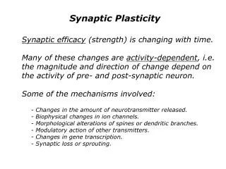
Crystal Plasticity
Crystal Plasticity. Class One. Window of resolution for dislocation plasticity. Dislocation patterns. Discrete dislocations. Atomistic. Grains. Macroscale. Molecular Dynamics. Discrete Dislocation Theory. Continuously Distributed Dislocation Theory. Crystal Plasticity.


Crystal Plasticity
E N D
Presentation Transcript
Crystal Plasticity Class One
Window of resolution for dislocation plasticity. Dislocation patterns Discrete dislocations Atomistic Grains Macroscale Molecular Dynamics Discrete Dislocation Theory Continuously Distributed Dislocation Theory Crystal Plasticity Continuum Plasticity • Polycrystal idealizations (grains with distributed defects – dislocations). Both scales of grain and sub-grain structures Grain scale heterogeneities Homogenized description The Multiscale Approach to Materials Modeling
By discarding the explicit representation of microstructure, the approach loses the capability to model the state of the material in terms of direct mapping between microstructure and properties. Typically used to solve large boundary value problems since the approach uses a reduced number of DOFs to represent the material response at each continuum point. Mechanical characterization tests and material parameter determination procedures play an important role. Fully homogenized description: effects of both grain and subgrain heterogeneities on the material response are implicitly modeled by ISVs. The Macroscale Approach to Materials Modeling Polycrystal Idealization Finite Element Model Mechanical Tests Test Data
Explicitly models discrete grains and slip systems, accounting then for the anisotropy of single crystal propertiesand crystallographic texture. Slip system level constitutive equations for dislocation glide kinetics and work hardening are based on phenomenological models. Uses relatively a large number of ISVs for hardening parameters, which implicitly address dislocation storage and interactions. Approach used to study aggregate of crystals to obtain a better understanding of polycrystal behavior better continuum plasticity models. unit cell More predictive and robust than macroscopic plasticity since it explicitly addresses evolution of crystallographic texture and models both anisotropic elasticity and plasticity. However, the approach is computationally expensive. lattice reference frame global reference frame A Mesoscale Approach to Materials Modeling:Crystal Plasticity FCC 12 slip systems m={111}, s=<110>
Why investigate crystal plasticity? • Behavior at the macrolevel, in particular “plastic anisotropy”, is controlled by • features (structure) at the microscopic level: crystals and dislocation within • crystals • (Poly)crystal plasticity provides a theory that links the constitutive response to • key microstructural features to model plastic anisotropy.These features are: • Anisotropy of single crystal properties (crystal structure/slip systems) • Crystallographic texture (totality of crystallite orientations) • Description of the theory: • Single Crystal: • Deformation modes of crystals slip systems • Stress needed to activate mode critical resolved shear stress (Schmid’s Law) • Re-orientation of single crystal (rotation) texture • Aggregate of Crystals (Polycrystals): • Average over aggregate: stresses and strains • Display of orientations (texture) pole figure
Classical crystal plasticity models needed to predict shape changes due to anisotropy of single crystal properties Single Crystaland Bicrystal Uniaxial Compression Experiments Bicrystal 7.3 mm Single Crystal =0.6 =0.6 Strain-Stress Response Inverse Pole Figure
EARING RD TD Classical crystal plasticity models also needed to predict texture effects on both the deformation mode and the stress response (plastic anisotropy) Deformation Mode Stress Response Plastic anisotropy can be measured by the strain ratioR:
Some Basic Considerations for Classical Crystal Plasticity Experimental technique: Uniaxial Tension or Compression Experimental measurements showed that • At room temperature the major source for plastic deformation is the dislocation motion through the crystal lattice • Dislocation motions (glide) occurs on certain crystal planes in certain crystallographic directions • The Crystal structure of metals is not altered by the plastic flow • Volume changes during plastic flow are negligible
predominant slip systems for some crystal structures c-axis HCP 12 slip systems Basal: m={0001}, s=<1120> Prismatic: m={1010}, s=<1120> BCC 12 slip systems m={110}, s=<111> FCC 12 slip systems m={111}, s=<110> - - - Single Crystal / Slip Behavior • We will assume that the deformation is accomodated within crystals by slip, • but we will not try to resolve dislocations. The “net” result of all dislocation • motion is a homogeneous deformation over a crystal that can be written as • a linear combination of shears (, =0) on dominant slip systems. • Slip systems are particular modes of deformation that are activated when • stresses are large enough to induce plastic deformation. Slip systems consist • of slip planes (m) and slip directions (s). There will be many of these slip • systems for each crystal (restricted glide). slip systems can be related to the crystal lattice orientation unit cell unit cell Slip Plane: plane of greatest atomic density Slip Direction: close-packed direction within the slip plane face-centered cubic crystal structure
Critical Resolved Shear Stress • A crystal deforms plastically when the stress component on a slip plane and • in the slip direction reaches a limiting value: critical resolved shear stress, i.e • Consider a single slip system material: (yield criterion) Stress acting on the slip plane / slip direction: } Schmid factor Yielding occurs when (Schmid’s Law): • For materials with multiple slip systems: • Stress tensor • Schmid tensor • The Schmid tensor: • Projects the stress onto the slip system. • Models the direction of plastic flow: •
Schmid’s Law: Summary • Initial yield stress varies from sample to sample depending on the position of the crystal lattice relative to the loading axis. • It is the shear stress resolved along the slip direction on the slip plane that initiates plastic deformation. • Yield will begin on a slip system when the shear stress on this system reaches a critical value (critical resolved shear stress, crss), independent of the tensile stress or any other normal stress on the lattice plane.
Experimental Validation of Schmid’s Law • The experimental evidence of Schmid’s Law is that there is a critical resolved shear stress. This is verified by measuring the yield stress of single crystals as a function of orientation. The example below is for Mg which is hexagonal and slips most readily on the basal plane (all other tcrss are much larger). “Soft orientation”,with slip plane at45°to tensile axis s = t/coslcosf “Hard orientation”,with slip plane at~90°to tensile axis
Schmid’s Law: Example Using Schmid’s Law:
Shear Stress – Shear Strain Curves • A typical flow curve (stress-strain) for a single crystal shows three stages: • Stage I : “easy glide” with low hardening rates; - Stage II : with high, constant hardening rate, nearly independent of temperature or strain rate; - Stage III : with decreasing hardening rate and very sensitive to temperature and strain rate.
Rate-sensitive model • The Schmid Law pictures the elastic-perfectly plastic behavior of a crystal. • In fact, there is a smooth transition from elastic to plastic behavior that can be described by a power-law behavior. • The shear strain rate on each slip system is given by the following (for a given stress state) • By assuming this kinetics of plastic flow (rate-sensitive), we avoid the • non-uniqueness of the set of active slip systems typically present in • rate-insensitive models. (review “Minimum Work Principle” – Taylor).
rotation crystal slip planes bending Crystal Reorientation • Why do the slip systems re-orient? (crystal lattice rotate?) • (a) The slip planes and slip directions in a crystal are finite in number and • fixed to the lattice. • (b) An arbitrary motion can only be accommodated, in general, by allowing • the crystal lattice to rotate. computing the crystal lattice reorientation geometrically unrestrained single crystal continued axial alignment of the crystal and tensile axis (BCs)
Texture Representation: Pole Figures • A crystal orientation is represented by its location on a unit sphere projected onto the unit circle. • Pole Figure Construction: Connect a line from the South pole to the point on the surface of the sphere. The intersection of the line with the equatorial plane defines the project point. The equatorial plane is the projection plane. The radius from the origin (center) of the sphere, r, where R is the radius of the sphere, and a is the angle from the North Pole vector to the point to be projected, is given by: r = R tan(a/2)
Inverse Pole Figure FCC materials There are 12 slip systems (with + and - shear directions): Four {111} planes, each with three <011> directions
aggregate crystal Polycrystal Plasticity Theory The Theory is built upon: • The physics of single crystal plastic deformation; • Relations between macroscopic and microscopic quantities ( strain, stress) Mean Field Hypothesis (Linking or Bridging Assumptions) Need for a Mean Field Hypothesis to build the Theory: At a continuum point: L (D, W) At an individual crystal: L (Dc,Wc )
Approximate Polycrystal Models Taylor Model (Upper Bound) • All single-crystal grains within the aggregate experience the same state of deformation (strain): L=Lc (D=Dc, W=Wc); c • Equilibrium condition across the grain boundaries violated. • Compatibility conditions between the grains assured. • The response represents an UPPER BOUND on the averaged stress in the polycrystalline aggregate. • Upper Bound Stiffness: • Aggregate stiffness is the average of • the single crystal stiffness tensors.
Approximate Polycrystal Models Sachs Model (Lower Bound) • All single-crystal grains with aggregate or polycrystal experience the same state of stress: = c; L=Lc (D=Dc, W= Wc ) • Equilibrium condition across the grain boundaries satisfied. • Compatibility conditions between the grains violated. • The response represents a LOWER BOUND on the averaged stress in the polycrystalline aggregate. • Lower Bound Stiffness: • Aggregate stiffness is the inverse of the average • of the single crystal compliance tensors.
Approximate Polycrystal ModelsHybrid Models • Just as implied, these models impose certain stress components at the crystal level equal their respective macroscopic values while the remaining components of the motion equal the macroscopic values • Examples • Constrained Hybrid Model (Parks & Ahzi) • Relaxed Constraints Model (Kocks et al.) • Self-Consistent Methods (Tome, Molinari, Canova, et al.)
Approximate Polycrystal ModelsYield Loci • Texture • Upper Bound Yield Surface • Lower Bound Yield Surface