Download
1 / 21
210 likes | 355 Vues
Amplitude Modulated Radio Frequency Transmission System. Instructor: Dr. Fu By: Megan Myles, David Jackson, and Edwin Wambwa. Introduction.

E N D
Amplitude Modulated Radio Frequency Transmission System Instructor: Dr. Fu By: Megan Myles, David Jackson, and Edwin Wambwa
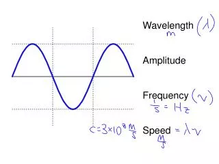
Introduction An amplitude modulated radio frequency transmission system consists of a modulator in which a sinusoidal high frequency carrier waveform cos(2πfct) is amplitude modulated (AM) by a lower frequency signal vm(t), containing the information to be transmitted. This is also known as the intelligence signal.
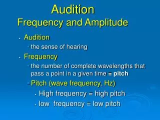
Modulation • There is only one sine wave at a given frequency, so how does the information get carried at a particular frequency? • Modulation = Encoding information on a signal • Analog radio modulation technologies: • FM = Frequency Modulation • AM = Amplitude Modulation • PM = Phase Modulation
AM/FM Difference • But AM can transmit over longer distances because AM frequencies bounce off ionosphere and diffract around hills and buildings but FM frequencies are absorbed, causing “shadows” • PM is analogous to FM.
Am Modulator/transmitter Tuned Circuit Receiver RF Amplifier Peak or envelope detector Audio Frequency Transistor Amplifier Frequency Spectrum of a AM signal Basic Principles of AM Radio Transmissions
LC Tuned Circuit • Inductor = 8.2 µH • Capacitor = .33 µF • Resonant Freq. = 96.75 kHz • Resistor = 1 kOhm
. AM Transmitter Block
Project Schematics • LC resonant frequency = 1Vp-p 96.75117220964837 kHz • Intelligence signal = 5 kHz, -1Vdc offset, 400mVp-p
AM Waveform Key • Yellow- Carrier Signal • Blue- Intelligence Signal • Purple- Transmitter output modulated waveform
AM Frequency Spectrum Key • Cursor 1- Center Frequency 96.75kHz • Cursor 2- Upper Sideband 101.7kHz
Transmitted AM signal 3dB cutoff difference between center and sidebands
Peak (Envelope) Detector . • Key • 2πfc > 1/R3C2 > 2πfi • 607905.5438 > 40000 > 31415.92654 • R3 = 2.5 kOhms • C2 = .01 µF
Trouble Shooting • AM envelope disappeared when transmitter was connected to receiver • Used resistors as a simulated test resistance for antenna • Receiver output signal obtained • Used potentiometer to fine tune antenna resistance • Receiver output matched original intelligence input .
Complete System/Recovered Intelligence . • Key • Yellow=carrier Input (1Vp-p, 96.75117220964837kHz) • Blue=intelligence input (400mVp-p, 5kHz, -1Vdc offset) • Purple= amplitude modulated transmitter output (20Vp-p, 96.75117220964837kHz) • Green=receiver output (400mVp-p, 5kHz, 90 degrees out of phasewith original intelligence)
Project costComponents and Parts: $55Some components were acquired from Yomi’s stock pile. Man Hours:Approx 60Hrs .
Challenges . • Sound output after designing a higher gain amplifier circuit (we designed for a single toned sound output). • Signal transmission using aerials instead of hard wiring the circuit. • Implementation of a tuning circuit (AFC) in order to receive an audible signal
Conclusions . The experiment was well understood and gave us a better insight into our understanding of AM and FM. We implemented similar labs throughout the course, but were able to combine methods of radio transmission into a complete transmission system.
Fin .