ELECTRIC CIRCUIT ANALYSIS - I
ELECTRIC CIRCUIT ANALYSIS - I. Chapter 17 – Methods of Analysis & Sel Topics Lecture 23 by Moeen Ghiyas. Today’s Lesson Contents. Independent vs Dependent Sources Source Conversions Mesh Analysis Bridge Networks. INDEPENDENT VERSUS DEPENDENT SOURCES. Independent Sources


ELECTRIC CIRCUIT ANALYSIS - I
E N D
Presentation Transcript
ELECTRIC CIRCUIT ANALYSIS - I Chapter 17 – Methods of Analysis & Sel Topics Lecture 23 by MoeenGhiyas
Today’s Lesson Contents • Independent vs Dependent Sources • Source Conversions • Mesh Analysis • Bridge Networks
INDEPENDENT VERSUS DEPENDENT SOURCES • Independent Sources • The term independent specifies that the magnitude of the source is independent of the network to which it is applied and that the source displays its terminal characteristics even if completely isolated.
INDEPENDENT VERSUS DEPENDENT SOURCES • Dependent (Controlled) Sources • A dependent or controlled source is one whose magnitude is determined (or controlled) by a current or voltage of the system in which it appears Old Symbols New Symbols
INDEPENDENT VERSUS DEPENDENT SOURCES • Dependent (Controlled) Sources • Unlike with the independent source, isolation such that V or I = 0 will result in short-circuit or open-circuit equivalent as indicated
SOURCE CONVERSIONS • Source conversion can be accomplished in much the same manner as for dc circuits, except now we shall be dealing with phasors and impedances instead of just real numbers and resistors
SOURCE CONVERSIONS • EXAMPLE - Convert the voltage source of fig to a current source • Solution:
SOURCE CONVERSIONS • EXAMPLE - Convert the current source of fig to a voltage source • Solution:
SOURCE CONVERSIONS • For dependent sources, the direct conversion can be applied if the controlling variable (V or I) is not determined by a portion of the network to which the conversion is to be applied • Conversions of the other kind, where V and I are controlled by a portion of the network to be converted, are covered in chapter 18 (Not part of syllabus for 2nd semester)
SOURCE CONVERSIONS • EXAMPLE - Convert the voltage source of fig to a current source • Solution:
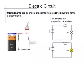
Mesh Analysis (General Approach) dc (ac) • Steps • Assign a distinct current direction to each independent, closed loop • Indicate the polarities within each loop for each resistor (impedance) . Note that the polarities be placed within each loop. Thus 4 Ω resistor have two sets of polarities across it.
Mesh Analysis (General Approach) • Steps • Apply Kirchhoff’s voltage law around each closed loop • the total current through the element (impedance) is the assumed current of the loop plus the assumed currents of the other loops passing through in the same direction, minus the assumed currents through in the opposite direction • The polarity of a voltage source is unaffected by the direction of the assigned loop currents • Solve the resulting simultaneous linear equations for the assumed loop currents
Mesh Analysis (General Approach) • The general approach to mesh includes the same sequence of steps as for dc except to substitute impedance for resistance and admittance for conductance in the general procedure with minor additional changes as mentioned below: • Independent Voltage Sources • Same as dc analysis with impedances and admittance values • Dependent Voltage Sources • Step 3 is modified: Treat each dependent source like an independent source when KVL is applied. However, once the equation is written, substitute the equation for the controlling quantity (i.e an additional eqn is generated for controlling qty)
Mesh Analysis (General Approach) • Independent Current Sources • Treat each current source as an open circuit (recall supermesh concept), and write mesh equations for remaining paths. • Then relate the chosen mesh currents to the independent sources to ensure that the unknowns of the final equations are limited simply to the mesh currents • Dependent Current Sources • The procedure is same as for independent current sources (i.e. supermesh concept), except now the dependent sources have to be defined in terms of the chosen mesh currents so that the final equations have only mesh currents as the unknown qtys.
Mesh Analysis (General Approach) • EXAMPLE - Using the general approach to mesh analysis, find the current I1 in Fig • Solution • The network is redrawn
Mesh Analysis (General Approach) • Apply KVL, Loop 1: +E1 – I1Z1 – I1Z2 + I2Z2 = 0 I1Z1 + I1Z2 - I2Z2 = E1 I1(Z1 + Z2) – I2Z2 = E1 ----- A Loop 2: – E2 – I2Z2 + I1Z2 – I2Z3 = 0 – I1Z2 + I2Z2 + I2Z3 = – E2 – I1Z2 + I2(Z2 + Z3) = – E2 ------ B • Solve by determinants
Mesh Analysis (General Approach) • Solve by determinants and then substitute values I1(Z1 + Z2) – I2Z2 = E1 – I1Z2 + I2(Z2 + Z3) = – E2
Mesh Analysis (General Approach) • EXAMPLE - Write the mesh currents for the network of fig having a dependent voltage source. • Solution:
Mesh Analysis (General Approach) • EXAMPLE - Write the mesh currents for the network of fig having a independent current source. • Solution: • Apply supermesh concept
Mesh Analysis (General Approach) • EXAMPLE - Write the mesh currents for the network of fig having a dependent current source. • Solution:
Mesh Analysis (General Approach) • Problem # 9 – Using mesh analysis, determine the current IL (in terms of V) for the network of fig • Solution:
Mesh Analysis (General Approach) • Problem # 9 – Using mesh analysis, determine the current IL (in terms of V) for the network of fig • Solution: • Solving by determinants
Bridge Networks (ac) • Bridge networks with reactive components & ac voltage or current • Maxwell’s Bridge (V source & RC parallel) • From dc we remember, for IZ5 = 0, the following condition must be met or
Bridge Networks (ac) • Hay Bridge (I source & RC series) • From dc we remember, for VZ5 = 0, the following condition must be met • or • or
Bridge Networks (ac) • Hay bridge – when Z5 is replaced by a sensitive galvanometer is used for measuring the resistance and inductance of coils in which the resistance is a small fraction of the reactance XL. • Maxwell bridge – when Z5 is replaced by a sensitive galvanometer is used for inductance measurements when the resistance of the coil is large enough not to require a Hay bridge.
Bridge Networks (ac) • Another popular bridge is the capacitance comparison bridge of fig. An unknown capacitance and its associated resistance can be determined using this bridge.
Summary / Conclusion • Independent vs Dependent Sources • Source Conversions • Mesh Analysis • Bridge Networks