Introduction to the Cell multiprocessor
160 likes | 163 Vues
Introduction to the Cell multiprocessor<br>

Introduction to the Cell multiprocessor
E N D
Presentation Transcript
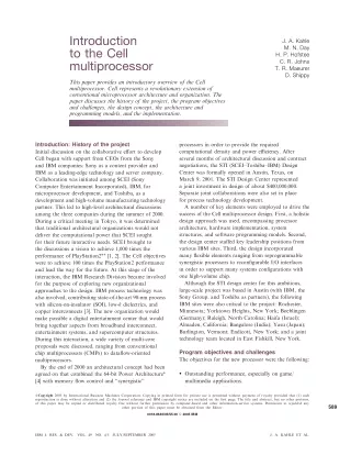
Introduction to the Cell multiprocessor J. A. Kahle M. N. Day H. P. Hofstee C. R. Johns T. R. Maeurer D. Shippy This paper provides an introductory overview of the Cell multiprocessor. Cell represents a revolutionary extension of conventional microprocessor architecture and organization. The paper discusses the history of the project, the program objectives and challenges, the design concept, the architecture and programming models, and the implementation. Introduction: History of the project Initial discussion on the collaborative effort to develop Cell began with support from CEOs from the Sony and IBM companies: Sony as a content provider and IBM as a leading-edge technology and server company. Collaboration was initiated among SCEI (Sony Computer Entertainment Incorporated), IBM, for microprocessor development, and Toshiba, as a development and high-volume manufacturing technology partner. This led to high-level architectural discussions among the three companies during the summer of 2000. During a critical meeting in Tokyo, it was determined that traditional architectural organizations would not deliver the computational power that SCEI sought for their future interactive needs. SCEI brought to the discussions a vision to achieve 1,000 times the performance of PlayStation2** [1, 2]. The Cell objectives were to achieve 100 times the PlayStation2 performance and lead the way for the future. At this stage of the interaction, the IBM Research Division became involved for the purpose of exploring new organizational approaches to the design. IBM process technology was also involved, contributing state-of-the-art 90-nm process with silicon-on-insulator (SOI), low-k dielectrics, and copper interconnects [3]. The new organization would make possible a digital entertainment center that would bring together aspects from broadband interconnect, entertainment systems, and supercomputer structures. During this interaction, a wide variety of multi-core proposals were discussed, ranging from conventional chip multiprocessors (CMPs) to dataflow-oriented multiprocessors. By the end of 2000 an architectural concept had been agreed on that combined the 64-bit Power Architecture* [4] with memory flow control and ‘‘synergistic’’ processors in order to provide the required computational density and power efficiency. After several months of architectural discussion and contract negotiations, the STI (SCEI–Toshiba–IBM) Design Center was formally opened in Austin, Texas, on March 9, 2001. The STI Design Center represented a joint investment in design of about $400,000,000. Separate joint collaborations were also set in place for process technology development. A number of key elements were employed to drive the success of the Cell multiprocessor design. First, a holistic design approach was used, encompassing processor architecture, hardware implementation, system structures, and software programming models. Second, the design center staffed key leadership positions from various IBM sites. Third, the design incorporated many flexible elements ranging from reprogrammable synergistic processors to reconfigurable I/O interfaces in order to support many systems configurations with one high-volume chip. Although the STI design center for this ambitious, large-scale project was based in Austin (with IBM, the Sony Group, and Toshiba as partners), the following IBM sites were also critical to the project: Rochester, Minnesota; Yorktown Heights, New York; Boeblingen (Germany); Raleigh, North Carolina; Haifa (Israel); Almaden, California; Bangalore (India); Yasu (Japan); Burlington, Vermont; Endicott, New York; and a joint technology team located in East Fishkill, New York. Program objectives and challenges The objectives for the new processor were the following: ? Outstanding performance, especially on game/ multimedia applications. ?Copyright 2005 by International Business Machines Corporation. Copying in printed form for private use is permitted without payment of royalty provided that (1) each reproduction is done without alteration and (2) the Journal reference and IBM copyright notice are included on the first page. The title and abstract, but no other portions, of this paper may be copied or distributed royalty free without further permission by computer-based and other information-service systems. Permission to republish any other portion of this paper must be obtained from the Editor. 589 0018-8646/05/$5.00 ª ª 2005 IBM IBM J. RES. & DEV. VOL. 49 NO. 4/5 JULY/SEPTEMBER 2005 J. A. KAHLE ET AL.
? Real-time responsiveness to the user and the network. ? Applicability to a wide range of platforms. ? Support for introduction in 2005. effectively by allowing more memory transactions to be in flight simultaneously. Power and power density in CMOS processors have increased steadily to a point at which we find ourselves once again in need of the sophisticated cooling techniques we had left behind at the end of the bipolar era [6]. However, for consumer applications, the size of the box, the maximum airspeed, and the maximum allowable temperature for the air leaving the system impose fundamental first-order limits on the amount of power that can be tolerated, independent of engineering ingenuity to improve the thermal resistance. With respect to technology, the situation is worse this time for two reasons. First, the dimensions of the transistors are now so small that tunneling through the gate and sub- threshold leakage currents prevent following constant- field scaling laws and maintaining power density for scaled designs [7]. Second, an alternative lower-power technology is not available. The challenge is therefore to find means to improve power efficiency along with performance [8]. A third barrier to improving performance stems from the observation that we have reached a point of diminishing return for improving performance by further increasing processor frequencies and pipeline depth [9]. The problem here is that when pipeline depths are increased, instruction latencies increase owing to the overhead of an increased number of latches. Thus, the performance gained by the increased frequency, and hence the ability to issue more instructions in any given amount of time, must exceed the time lost due to the increased penalties associated with the increased instruction execution latencies. Such penalties include instruction issue slots1that cannot be utilized because of dependencies on results of previous instructions and penalties associated with mispredicted branch instructions. When the increase in frequency cannot be fully realized because of power limitations, increased pipeline depth and therefore execution latency can degrade rather than improve performance. It is worth noting that processors designed to issue one or two instructions per cycle can effectively and efficiently sustain higher frequencies than processors designed to issue larger numbers of instructions per cycle. The challenge is therefore to develop processor microarchitectures and implementations that minimize pipeline depth and that can efficiently use the issue slots available to them. Outstanding performance, especially on game/multimedia applications The first of these objectives, outstanding performance, especially on game/multimedia applications, was expected to be challenged by limits on performance imposed by memory latency and bandwidth, power (even more than chip size), and diminishing returns from increased processor frequencies achieved by reducing the amount of work per cycle while increasing pipeline depth. The first major barrier to performance is increased memory latency as measured in cycles, and latency- induced limits on memory bandwidth. Also known as the ‘‘memory wall’’ [5], the problem is that higher processor frequencies are not met by decreased dynamic random access memory (DRAM) latencies; hence, the effective DRAM latency increases with every generation. In a multi-GHz processor it is common for DRAM latencies to be measured in the hundreds of cycles; in symmetric multiprocessors with shared memory, main memory latency can tend toward a thousand processor cycles. A conventional microprocessor with conventional sequential programming semantics will sustain only a limited number of concurrent memory transactions. In a sequential model, every instruction is assumed to be completed before execution of the next instruction begins. If a data or instruction fetch misses in the caches, resulting in an access to main memory, instruction processing can only proceed in a speculative manner, assuming that the access to main memory will succeed. The processor must also record the non-speculative state in order to safely be able to continue processing. When a dependency on data from a previous access that missed in the caches arises, even deeper speculation is required in order to continue processing. Because of the amount of administration required every time computation is continued speculatively, and because the probability that useful work is being speculatively completed decreases rapidly with the number of times the processor must speculate in order to continue, it is very rare to see more than a few speculative memory accesses being performed concurrently on conventional microprocessors. Thus, if a microprocessor has, e.g., eight 128-byte cache-line fetches in flight (a very optimistic number) and memory latency is 1,024 processor cycles, the maximum sustainable memory bandwidth is still a paltry one byte per processor cycle. In such a system, memory bandwidth limitations are latency-induced, and increasing memory bandwidth at the expense of memory latency can be counterproductive. The challenge therefore is to find a processor organization that allows for more memory bandwidth to be used Real-time responsiveness to the user and the network From the beginning, it was envisioned that the Cell processor should be designed to provide the best possible 590 1An instruction issue slot is an opportunity to issue an instruction. J. A. KAHLE ET AL. IBM J. RES. & DEV. VOL. 49 NO. 4/5 JULY/SEPTEMBER 2005
experience to the human user and the best possible response to the network. This ‘‘outward’’ focus differs from the ‘‘inward’’ focus of processor organizations that stem from the era of batch processing, when the primary concern was to keep the central processor unit busy. As all game developers know, keeping the players satisfied means providing continuously updated (real-time) modeling of a virtual environment with consistent and continuous visual and sound and other sensory feedback. Therefore, the Cell processor should provide extensive real-time support. At the same time we anticipated that most devices in which the Cell processor would be used would be connected to the (broadband) Internet. At an early stage we envisioned blends of the content (real or virtual) as presented by the Internet and content from traditional game play and entertainment. This requires concurrent support for real-time operating systems and the non-real-time operating systems used to run applications to access the Internet. Being responsive to the Internet means not only that the processor should be optimized for handling communication-oriented workloads; it also implies that the processor should be responsive to the types of workloads presented by the Internet. Because the Internet supports a wide variety of standards, such as the various standards for streaming video, any acceleration function must be programmable and flexible. With the opportunities for sharing data and computation power come the concerns of security, digital rights management, and privacy. allow us to deliver impressive processor performance, responsiveness to the user and network, and the flexibility to ensure a broad reach, and to do this without making a complete break with the past. Indications were that a completely new architecture can easily require ten years to develop, especially if one includes the time required for software development. Hence, the Power Architecture* was used as the basis for Cell. Design concept and architecture The Broadband Processor Architecture extends the 64-bit Power Architecture with cooperative offload processors (‘‘synergistic processors’’), with the direct memory access (DMA) and synchronization mechanisms to communicate with them (‘‘memory flow control’’), and with enhancements for real-time management. The first-generation Cell processor (Figure 1) combines a dual-threaded, dual-issue, 64-bit Power-Architecture- compliant Power processor element (PPE) with eight newly architected synergistic processor elements (SPEs) [11], an on-chip memory controller, and a controller for a configurable I/O interface. These units are interconnected with a coherent on-chip element interconnect bus (EIB). Extensive support for pervasive functions such as power-on, test, on-chip hardware debug, and performance-monitoring functions is also included. The key attributes of this concept are the following: ? A high design frequency (small number of gates per cycle), allowing the processor to operate at a low voltage and low power while maintaining high frequency and high performance. ? Power Architecture compatibility to provide a conventional entry point for programmers, for virtualization, multi-operating-system support, and the ability to utilize IBM experience in designing and verifying symmetric multiprocessors. ? Single-instruction, multiple-data (SIMD) architecture, supported by both the vector media extensions on the PPE and the instruction set of the SPEs, as one of the means to improve game/media and scientific performance at improved power efficiency. ? A power- and area-efficient PPE that supports the high design frequency. ? SPEs for coherent offload. SPEs have local memory, asynchronous coherent DMA, and a large unified register file to improve memory bandwidth and to provide a new level of combined power efficiency and performance. The SPEs are dynamically configurable to provide support for content protection and privacy. Applicability to a wide range of platforms The Cell project was driven by the need to develop a processor for next-generation entertainment systems. However, a next-generation architecture with strength in the game/media arena that is designed to interface optimally with a user and broadband network in real time could, if architected and designed properly, be effective in a wide range of applications in the digital home and beyond. The Broadband Processor Architecture [10] is intended to have a life well beyond its first incarnation in the first-generation Cell processor. In order to extend the reach of this architecture, and to foster a software development community in which applications are optimized to this architecture, an open (Linux**-based) software development environment was developed along with the first-generation processor. Support for introduction in 2005 The objective of the partnership was to develop this new processor with increased performance, responsiveness, and security, and to be able to introduce it in 2005. Thus, only four years were available to meet the challenges outlined above. A concept was needed that would 591 IBM J. RES. & DEV. VOL. 49 NO. 4/5 JULY/SEPTEMBER 2005 J. A. KAHLE ET AL.
between the processor elements. The bus is coherent to allow a single address space to be shared by the PPEs and SPEs for efficient communication and ease of programming. ? High-bandwidth flexible I/O configurable to support a number of system organizations, including a single- chip configuration with dual I/O interfaces and a ‘‘glueless’’ coherent dual-processor configuration that does not require additional switch chips to connect the two processors. ? Full-custom modular implementation to maximize performance per watt and performance per square millimeter of silicon and to facilitate the design of derivative products. ? Extensive support for chip power and thermal management, manufacturing test, hardware and software debugging, and performance analysis. ? High-performance, low-cost packaging technology. ? High-performance, low-power 90-nm SOI technology. SPE SXU SXU SXU SXU SXU SXU SXU SXU LS LS LS LS LS LS LS LS DMA DMA DMA DMA DMA DMA DMA DMA On-chip coherent bus (up to 96 bytes per cycle) PPE L2 Memory controller Bus interface controller Power core Dual Rambus XDR** Rambus FlexIO** L1 (a) Rambus XDR DRAM interface Rambus XDR DRAM interface Rambus XDR DRAM interface Memory controller Memory controller Memory controller L2 L2 L2 0.5 MB 0.5 MB 0.5 MB Power Power Power core core core High design frequency and low supply voltage To deliver the greatest possible performance, given a silicon and power budget, one challenge is to co-optimize the chip area, design frequency, and product operating voltage. Since efficiency improves dramatically (faster than quadratic) when the supply voltage is lowered, performance at a power budget can be improved by using more transistors (larger chip) while lowering the supply voltage. In practice the operating voltage has a minimum, often determined by on-chip static RAM, at which the chip ceases to function correctly. This minimum operating voltage, the size of the chip, the switching factors that measure the percentage of transistors that will dissipate switching power in a given cycle, and technology parameters such as capacitance and leakage currents determine the power the processor will dissipate as a function of processor frequency. Conversely, a power budget, a given technology, a minimum operating voltage, and a switching factor allow one to estimate a maximum operating frequency for a given chip size. As long as this frequency can be achieved without making the design so inefficient that one would be better off with a smaller chip operating at a higher supply voltage, this is the design frequency the project should aim to achieve. In other words, an optimally balanced design will operate at the minimum voltage supported by the circuits and at the maximum frequency at that minimum voltage. The chip should not exceed the maximum power tolerated by the application. In the case of the Cell processor, having eliminated most of the barriers that cause inefficiency in high-frequency designs, the initial design objective was a cycle time no more than that of ten fan-out-of-four Test and debug logic Test and debug logic Test and debug logic SPE SPE SPE SPE SPE SPE Coherent bus Coherent bus Coherent bus SPE SPE SPE SPE SPE SPE SPE SPE SPE SPE SPE SPE SPE SPE SPE SPE SPE SPE I/O controller I/O controller I/O controller Rambus RRAC Rambus RRAC Rambus RRAC (b) Figure 1 (a) Cell processor block diagram and (b) die photo. The first generation Cell processor contains a power processor element (PPE) with a Power core, first- and second-level caches (L1 and L2), eight synergistic processor elements (SPEs) each containing a direct memory access (DMA) unit, a local store memory (LS) and execution units (SXUs), and memory and bus interface controllers, all interconnected by a coherent on-chip bus. (Cell die photo courtesy of Thomas Way, IBM Burlington.) ? A high-bandwidth on-chip coherent bus and high bandwidth memory to deliver performance on memory-bandwidth-intensive applications and to allow for high-bandwidth on-chip interactions 592 J. A. KAHLE ET AL. IBM J. RES. & DEV. VOL. 49 NO. 4/5 JULY/SEPTEMBER 2005
inverters (10 FO4). This was later adjusted to 11 FO4 when it became clear that removing that last FO4 would incur a substantial area and power penalty. microarchitecture and floorplan of this processor avoid long wires and limit the amount of communication delay in every cycle and can therefore be characterized as ‘‘short-wire.’’ The design of the PPE is simplified in comparison to more recent four-issue out-of-order processors. The PPE is a dual-issue design that does not dynamically reorder instructions at issue time (e.g., ‘‘in- order issue’’). The core interleaves instructions from two computational threads at the same time to optimize the use of issue slots, maintain maximum efficiency, and reduce pipeline depth. Simple arithmetic functions execute and forward their results in two cycles. Owing to the delayed-execution fixed-point pipeline, load instructions also complete and forward their results in two cycles. A double-precision floating-point instruction executes in ten cycles. The PPE supports a conventional cache hierarchy with 32-KB first-level instruction and data caches and a 512-KB second-level cache. The second-level cache and the address-translation caches use replacement management tables to allow the software to direct entries with specific address ranges at a particular subset of the cache. This mechanism allows for locking data in the cache (when the size of the address range is equal to the size of the set) and can also be used to prevent overwriting data in the cache by directing data that is known to be used only once at a particular set. Providing these functions enables increased efficiency and increased real-time control of the processor. The processor provides two simultaneous threads of execution within the processor and can be viewed as a two-way multiprocessor with shared dataflow. This gives software the effective appearance of two independent processing units. All architected states are duplicated, including all architected registers and special-purpose registers, with the exception of registers that deal with system-level resources, such as logical partitions, memory, and thread control. Non-architected resources such as caches and queues are generally shared for both threads, except in cases where the resource is small or offers a critical performance improvement to multithreaded applications. The processor is composed of three units [Figure 2(a)]. The instruction unit (IU) is responsible for instruction fetch, decode, branch, issue, and completion. A fixed- point execution unit (XU) is responsible for all fixed- point instructions and all load/store-type instructions. A vector scalar unit (VSU) is responsible for all vector and floating-point instructions. The IU fetches four instructions per cycle per thread into an instruction buffer and dispatches the instructions from this buffer. After decode and dependency checking, instructions are dual-issued to an execution unit. A 4-KB by 2-bit branch history table with 6 bits of global Power Architecture compatibility The Broadband Processor Architecture maintains full compatibility with 64-bit Power Architecture [4]. The implementation on the Cell processor has aimed to include all recent innovations of Power technology such as virtualization support and support for large page sizes. By building on Power and by focusing the innovation on those aspects of the design that brought new advantages, it became feasible to complete a complex new design on a tight schedule. In addition, compatibility with the Power Architecture provides a base for porting existing software (including the operating system) to Cell. Although additional work is required to unlock the performance potential of the Cell processor, existing Power applications can be run on the Cell processor without modification. Single-instruction, multiple-data architecture The Cell processor uses a SIMD organization in the vector unit on the PPE and in the SPEs. SIMD units have been demonstrated to be effective in accelerating multimedia applications and, because all mainstream PC processors now include such units, software support, including compilers that generate SIMD instructions for code not explicitly written to use SIMD, is maturing. By opting for the SIMD extensions in both the PPE and the SPE, the task of developing or migrating software to Cell has been greatly simplified. Typically, an application may start out to be single-threaded and not to use SIMD. A first step to improving performance may be to use SIMD on the PPE, and a typical second step is to make use of the SPEs. Although the SIMD architecture on the SPEs differs from the one on the PPE, there is enough overlap so that programmers can reasonably construct programs that deliver consistent performance on both the PPE and (after recompilation) on the SPEs. Because the single-threaded PPE provides a debugging and testing environment that is (still) most familiar, many programmers prefer this type of approach to programming Cell. Power processor element The PPE (Figure 2) is a 64-bit Power-Architecture- compliant core optimized for design frequency and power efficiency. While the processor matches the 11 FO4 design frequency of the SPEs on a fully compliant Power processor, its pipeline depth is only 23 stages, significantly less than what one might expect for a design that reduces the amount of time per stage by nearly a factor of 2 compared with earlier designs [12, 13]. The 593 IBM J. RES. & DEV. VOL. 49 NO. 4/5 JULY/SEPTEMBER 2005 J. A. KAHLE ET AL.
IU 8 Pre-decode Threads alternate fetch and dispatch cycles Fetch control L1 instruction cache Thread A L2 Thread B interface 4 4 Branch scan SMT dispatch (queue) Microcode 2 1 Decode Dependency Issue 2 Thread A Thread B Thread A L1 data cache 1 1 1 VSU VMX/FPU issue (queue) 2 1 Branch execution unit Load/store unit Fixed-point unit 1 1 1 VMX VMX FPU FPU Completion/flush XU load/store/permute arith./logic unit arith./logic unit load/store FPU completion VMX completion (a) PPE pipeline front end MC1 MC2 MC3 MC4 ... MC9 MC10 MC11 Microcode Instruction cache and buffer IC1 IC2 IC3 IC4 IB1 IB2 ID1 ID2 ID3 IS1 IS2 IS3 Instruction decode and issue BP1 BP2 BP3 BP4 Branch prediction PPE pipeline back end Branch instruction IC IB BP MC ID IS DLY RF EX WB Instruction cache Instruction buffer Branch prediction Microcode Instruction decode Instruction issue Delay stage Register file access Execution Write back DLY DLY DLY RF1 RF2 EX1 EX2 EX3 EX4 IBZ IC0 Fixed-point unit instruction DLY DLY DLY RF1 RF2 EX1 EX2 EX3 EX4 EX5 WB Load/store instruction RF1 RF2 EX1 EX2 EX3 EX4 EX5 EX6 EX7 EX8 WB (b) Figure 2 Power processor element (a) major units and (b) pipeline diagram. Instruction fetch and decode fetches and decodes four instructions in parallel from the first-level instruction cache for two simultaneously executing threads in alternating cycles. When both threads are active, two instructions from one of the threads are issued in program order in alternate cycles. The core contains one instance of each of the major execution units (branch, fixed-point, load/store, floating-point (FPU), and vector-media (VMX). Processing latencies are indicated in part (b) [color-coded to correspond to part (a)]. Simple fixed-point instructions execute in two cycles. Because execution of fixed-point instructions is delayed, load to use penalty is limited to one cycle. Branch miss penalty is 23 cycles and is comparable to the penalty in designs with a much lower operating frequency. 594 J. A. KAHLE ET AL. IBM J. RES. & DEV. VOL. 49 NO. 4/5 JULY/SEPTEMBER 2005
history per thread is used to predict the outcome of branches. The IU can issue up to two instructions per cycle. All dual-issue combinations are possible except for two instructions to the same unit and the following exceptions. Simple vector, complex vector, vector floating-point, and scalar floating-point arithmetic cannot be dual-issued with the same type of instructions (for example, a simple vector with a complex vector is not allowed). However, these instructions can be dual-issued with any other form of load/store, fixed-point branch, or vector-permute instruction. A VSU issue queue decouples the vector and floating-point pipelines from the remaining pipelines. This allows vector and floating-point instructions to be issued out of order with respect to other instructions. The XU consists of a 32- by 64-bit general-purpose register file per thread, a fixed-point execution unit, and a load/store unit. The load/store unit consists of the L1 D-cache, a translation cache, an eight-entry miss queue, and a 16-entry store queue. The load/store unit supports a non-blocking L1 D-cache which allows cache hits under misses. The VSU floating-point execution unit consists of a 32- by 64-bit register file per thread, as well as a ten-stage double-precision pipeline. The VSU vector execution units are organized around a 128-bit dataflow. The vector unit contains four subunits: simple, complex, permute, and single-precision floating point. There is a 32-entry by 128-bit vector register file per thread, and all instructions are 128-bit SIMD with varying element width (2364-bit, 4 3 32-bit, 8 3 16-bit, 16 3 8-bit, and 128 3 1-bit). in the system (with the appropriate privilege) by using store or DMA-write commands. For programming convenience, and to allow local-store-to-local-store DMA transactions, the local store is mapped into the memory map of the processor, but this memory (if cached) is not coherent in the system. The local store organization introduces another level of memory hierarchy beyond the registers that provide local storage of data in most processor architectures. This is to provide a mechanism to combat the ‘‘memory wall,’’ since it allows for a large number of memory transactions to be in flight simultaneously without requiring the deep speculation that drives high degrees of inefficiency on other processors. With main memory latency approaching a thousand cycles, the few cycles it takes to set up a DMA command becomes acceptable overhead to access main memory. Obviously, this organization of the processor can provide good support for streaming, but because the local store is large enough to store more than a simple streaming kernel, a wide variety of programming models can be supported, as discussed later. The local store is the largest component in the SPE, and it was important to implement it efficiently [14]. A single-port SRAM cell is used to minimize area. In order to provide good performance, in spite of the fact that the local store must arbitrate among DMA reads, writes, instruction fetches, loads, and stores, the local store was designed with both narrow (128-bit) and wide (128-byte) read and write ports. The wide access is used for DMA reads and writes as well as instruction (pre)fetch. Because a typical 128-byte DMA read or write requires 16 processor cycles to place the data on the on-chip coherent bus, even when DMA reads and writes occur at full bandwidth, seven of every eight cycles remain available for loads, stores, and instruction fetch. Similarly, instructions are fetched 128 bytes at a time, and pressure on the local store is minimized. The highest priority is given to DMA commands, the next highest priority to loads and stores, and instruction (pre)fetch occurs whenever there is a cycle available. A special no- operation instruction exists to force the availability of a slot to instruction fetch when necessary. The execution units of the SPU are organized around a 128-bit dataflow. A large register file with 128 entries provides enough entries to allow a compiler to reorder large groups of instructions in order to cover instruction execution latencies. There is only one register file, and all instructions are 128-bit SIMD with varying element width (2364-bit, 4332-bit, 8316-bit, 1638-bit, and 1283 1-bit).Uptotwoinstructionsareissuedpercycle;oneissue slot supports fixed- and floating-point operations and the other provides loads/stores and a byte permutation operation as well as branches. Simple fixed-point operations take two cycles, and single-precision floating- Synergistic processing element The SPE [11] implements a new instruction-set architecture optimized for power and performance on computing-intensive and media applications. The SPE (Figure 3) operates on a local store memory (256 KB) that stores instructions and data. Data and instructions are transferred between this local memory and system memory by asynchronous coherent DMA commands, executed by the memory flow control unit included in each SPE. Each SPE supports up to 16 outstanding DMA commands. Because these coherent DMA commands use the same translation and protection governed by the page and segment tables of the Power Architecture as the PPE, addresses can be passed between the PPE and SPEs, and the operating system can share memory and manage all of the processing resources in the system in a consistent manner. The DMA unit can be programmed in one of three ways: 1) with instructions on the SPE that insert DMA commands in the queues; 2) by preparing (scatter- gather) lists of commands in the local store and issuing a single ‘‘DMA list’’ of commands; or 3) by inserting commands in the DMA queue from another processor 595 IBM J. RES. & DEV. VOL. 49 NO. 4/5 JULY/SEPTEMBER 2005 J. A. KAHLE ET AL.
Floating-point unit Permute unit Load/store unit Branch unit Channel unit Fixed-point unit 8 bytes per cycle 16 bytes per cycle 64 bytes per cycle 128 bytes per cycle Local store (256 KB) Single-port SRAM Result forwarding and staging Register file Instruction issue unit/instruction line buffer 128B read 128B write On-chip coherent bus DMA unit (a) SPE pipeline front end IF1 IF2 IF3 IF4 IF5 IB1 IB2 ID1 ID2 ID3 IS1 IS2 SPE pipeline back end Branch instruction RF1 RF2 IF IB ID IS RF EX WB Instruction fetch Instruction buffer Instruction decode Instruction issue Register file access Execution Write back Permute instruction EX1 EX2 EX3 EX4 WB Load/store instruction EX1 EX2 EX3 EX4 EX5 EX6 WB Fixed-point instruction EX1 EX2 WB Floating-point instruction EX1 EX2 EX3 EX4 EX4 EX6 WB (b) Figure 3 Synergistic processor element (a) organization and (b) pipeline diagram. Central to the synergistic processor is the 256-KB local store SRAM. The local store supports both 128-byte access from direct memory access (DMA) read and write, as well as instruction fetch, and a 16-byte interface for load and store operations. The instruction issue unit buffers and pre-fetches instructions and issues up to two instructions per cycle. A 6-read, 2-write port register file provides both execution pipes with 128-bit operands and stores the results. Instruction execution latency is two cycles for simple fixed-point instructions and six cycles for both load and single-precision floating-point instructions. Instruc- tions are staged in an operand-forwarding network for up to six additional cycles; all execution units write their results in the register file in the same stage. The penalty for mispredicted branches is 18 cycles. point and load instructions take six cycles. Two-way SIMD double-precision floating point is also supported, but the maximum issue rate is one SIMD instruction per seven cycles. All other instructions are fully pipelined. To limit hardware overhead for branch speculation, branches can be ‘‘hinted’’ by the programmer or compiler. The branch hint instruction notifies the hardware of an upcoming branch address and branch target, and the hardware responds (assuming that local store slots are available) by pre-fetching at least seventeen instructions at the branch target address. A three-source bitwise select instruction can be used to further eliminate branches from the code. The control area makes up only 10–15% of the area of the 10-mm2SPE core, and yet several applications achieve near-peak performance on this processor. The entire SPE is only 14.5 mm2and dissipates only a few watts even when operating at multi-GHz frequencies. High-bandwidth on-chip coherent fabric and high-bandwidth memory With the architectural improvements that remove the latency-induced limitation on bandwidth, the next challenge is to make significant improvements in delivering bandwidth to main memory and bandwidth between the processing elements and interfaces within the 596 J. A. KAHLE ET AL. IBM J. RES. & DEV. VOL. 49 NO. 4/5 JULY/SEPTEMBER 2005
Cell processor. Memory bandwidth at a low system cost is improved on the first-generation Cell processor by using next-generation Rambus XDR**DRAM memory [15]. This memory delivers 12.8 GB/s per 32-bit memory channel, and two of these channels are supported on the Cell processor for a total bandwidth of 25.6 GB/s. Since the internal fabric on the chip delivers nearly an order of magnitude more bandwidth (96 bytes per cycle at peak), there is almost no perceivable contention on DMA transfers between units within the chip. XDR XDR Cell processor IOIF0 IOIF1 (a) XDR XDR XDR XDR Cell Cell processor processor High-bandwidth flexible I/O In order to build effective dual-processor systems and systems with a high-bandwidth I/O-connected accelerator as well as an I/O-connected system interface chip, Cell is designed with a high-bandwidth configurable I/O interface. At the physical layer, a total of seven transmit and five receive Rambus RRAC FlexIO** bytes [16] can be dedicated to up to two separate logical interfaces, one of which can be configured to operate as a coherent interface. Thus, the Cell processor supports multiple high-bandwidth system configurations (Figure 4). IOIF BIF (b) IOIF XDR XDR XDR XDR Cell Cell processor processor IOIF IOIF BIF Switch BIF IOIF IOIF Cell Cell processor processor Full-custom implementation The first-generation Cell processor is a highly optimized full-custom high-frequency, low-power implementation of the architecture [17]. Cell is a system on a chip; however, unlike most SoCs, Cell has been designed with a full-custom design methodology. Some aspects of the physical design stand out in comparison with previous full-custom efforts: XDR XDR XDR XDR (c) Figure 4 Cell system configuration options: (a) Base configuration for small systems. (b) “Glueless” two-way symmetric multiprocessor. (c) Four-way symmetric multiprocessor. (IOIF: Input–output interface; BIF: broadband interface.) ? Several latch families, ranging from a more conventional static latch to a dynamic latch with integrated function to a pulsed latch that minimizes insertion delay. Most chip designs standardize on a single latch type and do not achieve the degree of optimization that is possible with this wide a choice. To manage the design and timing complexities associated with such a large number of latches, all latches share a common block that generates the local clocking signals that control the latch elements. The latches support only limited use of cycle-stealing, simplifying the design process. ? Extensive custom design on the wires. Several of the larger buses are fully engineered, controlling wiring levels and wire placement and using noise-reduction techniques such as wire twisting, and can be regarded as full-custom wire-only macros. A large fraction of the remaining wires are manually controlled to run preferentially on specific wiring layers. With transistors improving more rapidly than wires from one technology to the next, more of the engineering resource must be spent on managing and controlling wires than in the past. ? A design methodology which ensures that synthesized (usually control logic) macros are modified, timed, and analyzed at the transistor level consistently with custom designs. This allows macros to be changed smoothly from synthesized to custom. Among other advantages, this requires all macros to have corresponding transistor schematics. ? Extensive chip electrical and thermal engineering for power distribution and heat dissipation. Whereas previous projects would do the bulk of this analysis on the basis of static models, this project required pattern (program)-dependent analysis of the power dissipation and used feedback from these analysis tools to drive the design. Fine-grained clock gating was utilized to activate sections of logic only when they were needed. Multiple thermal sensors in the chip 597 IBM J. RES. & DEV. VOL. 49 NO. 4/5 JULY/SEPTEMBER 2005 J. A. KAHLE ET AL.
support in general, hardware debug, and thermal and power management and monitoring.The design allows cycle-by-cycle control of the various latch states (‘‘holding,’’ ‘‘scanning,’’ or ‘‘functional’’) at the full processor frequency. This allows management of switching power during scan-based test, facilitates scan- based at-speed test and debug, and enables functional thermal and power management on a partition basis. The design of the test interfaces is standardized and distributed. Both scan and built-in self test are accessed in this way. Generally each element contains a satellite- pervasive unit that interfaces with the various scan chains inside the unit and allows for communication with the built-in test functions in that unit. This modular and hierarchical organization facilitates the design of processors with a varying number of processor elements as well as creating other variations on the original design, such as modifying the external interfaces. Beyond the interfaces for test and scan-based hardware debug, an interface is provided to allow the units to present sequences of internal events to a central unit where these events can be correlated, counted, compared, or stored. This interface supports higher levels of hardware debug and can be used to provide detailed hardware-based performance measurements as well as other diagnostics. Finally, the pervasive logic contains the thermal management of the processor, including a network of thermal sensors, and the clocking controls to individually manage the levels of activity in various parts of the Cell chip. Lid Chip 3–2–3 Laminate Decoupling capacitor (a) (b) Figure 5 (a) Module cross section and (b) top-side bottom photo (top side without lid). (Photo courtesy of Thomas Way, IBM Burlington.) High-performance, low-cost packaging technology A new high-performance, low-cost package was developed for the Cell processor. The flip-chip plastic ball grid array (FC PBGA) package (Figure 5) employs a novel thin-core organic laminate design for efficient power distribution to the chip. The package design affords an extremely low core noise floor despite the large switching current and extensive utilization of power- management functions on the chip which trigger unusual noise events. Careful layout of the high-speed signal distribution in the package enables an aggregate I/O bandwidth in excess of 85 GB/s. allow much more detailed thermal management than was common in previous state-of-the-art designs. ? A focus on modularity in the physical design and interfaces such that derivative products with varying numbers of PPEs and SPEs can be constructed with significantly reduced effort. Standardized interfaces include not only the on-chip coherent bus, but also interfaces for test and hardware debug functions. Clock distribution, power distribution, and C4 placement are modular, so that the SPE has to be integrated only once. ? Multiple highly engineered clock grids. Whereas multiple clocks are commonly used in ASIC SoCs, it is not common to have multiple highly engineered clock distributions with skews controlled to about 10 ps. High-performance, low-power CMOS SOI technology The Cell processor uses a 90-nm CMOS SOI technology [3] that delivers both high performance and low power. It delivers high-performance SOI transistors through the use of strained silicon and high-performance interconnect through the use of a level of dense local interconnect wiring, eight additional levels of copper wiring, and low-k dielectrics. Extensive pervasive functionality The Cell processor includes a significant amount of circuitry to support power-on reset and self test, test 598 J. A. KAHLE ET AL. IBM J. RES. & DEV. VOL. 49 NO. 4/5 JULY/SEPTEMBER 2005
Programming models and programmability Whereas innovation in architectures can unlock new levels of performance and/or power efficiency, it must be possible to achieve good performance with a reasonable amount of programming effort if potential improvements are to be realized. Programmability was a consideration in the Cell processor at an early stage, and while this concern has not prevented us from making radical change where necessary to address fundamental performance limitations, a concerted effort was made to make the system as easily programmable and accessible as possible. Quite clearly, the aspect of the Cell processor that presents the greatest challenge to programmers, and often the greatest opportunities for increased application performance, is the existence of the local store memory and the fact that software must manage this memory. Over time this task may effectively be handled by a compiler, but at present the task of managing memory falls primarily to the programmer or library writer. The second aspect of the design that affects the programming model is the SIMD nature of the dataflows. Programmers can ignore this aspect of the design, but in doing so they may often leave a significant amount of performance on the table. Still, it is important to note that as with PC processors that implement SIMD units and do not always use them, an SPE can be programmed as a conventional scalar processor for applications that are not easily SIMD-vectorized. The SIMD aspects of the SPE are handled by programmers and supported by compilers in much the same way as the SIMD units on PC processors, with much the same benefits, and we do not elaborate on this aspect of the design here. The SPE differs from conventional microprocessors in a number of other ways, most significantly in the size of the register file (128 entries), the way branches are handled (and avoided), and some instructions that allow software to assist the arbitration on the local store and instruction issue. These aspects of the SPE can be effectively leveraged or handled by the compiler, and while a programmer who wants to obtain maximal performance can benefit from awareness of these mechanisms, it is almost never needed to program the SPE in assembly language. A final aspect of the SPE that differentiates it from conventional processors is the fact that only a single program context is supported at any time. This context can be a thread in an application (problem state) or a thread in a privileged (supervisor) mode, extending the operating system. The Cell processor supports virtualization and allows multiple operating systems to run concurrently on top of virtualization software running in ‘‘hypervisor’’ state. The SPEs can even be used to support hypervisor functionality. The fact that the SPE supports only one context we believe will generally be managed by the operating system; and just as most programmers of uniprocessors are only occasionally aware of the fact that the operating system will from time to time take execution time (and cache content) away from their application, most programmers may not realize that the SPEs are managed by an operating system running on a different processor. Incorporating a Power-Architecture-compliant core as the control processor enables Cell to run existing 32-bit and 64-bit Power and PowerPC applications without modification. However, in order to obtain the performance and power efficiency advantages of Cell, utilization of the SPE is required. The rich set of processor–processor communication and data movement facilities incorporated in the Cell processor make a wide range of programming models feasible. For example, it is possible for existing applications to use the SPEs rather transparently by utilizing a function offload model, with the SPE code providing acceleration to specific performance-critical library functions. Supporting many of these various programming models in a high-level language (such as C) played an integral part in the development of the Cell architecture. Many significant changes to the architectural definition of Cell were made in response to programmability concerns. Test programs, function libraries, operating system extensions, and applications were written, analyzed, and verified on a functional simulator prior to finalizing the architecture and implementation of Cell. In the following sections, we briefly describe a number of proposed programming models. Function offload model The function offload model may be the quickest model to deploy while effectively using features of the Cell processor. In this programming model, the SPEs are used as accelerators for certain types of performance-critical functions. The main application may be a new or existing application that executes on the PPE. This model replaces complex or performance-critical library functions (possibly supplied by a third party) invoked by the main application with functions offloaded into one or more SPEs. The main application logic is not changed at all. The original library function is optimized and recompiled for the SPE environment, and the SPE-executable program is bound into a PPE object module in a read-only section along with a small remote function invocation stub. This library is then loaded in the standard manner as an application dependency. When an application program running on a PPE makes the library function call, the remote procedure call stub in the library executes on the PPE and invokes the procedure in the SPE subsystem. Currently, the programmer statically identifies which functions should execute on the PPE 599 IBM J. RES. & DEV. VOL. 49 NO. 4/5 JULY/SEPTEMBER 2005 J. A. KAHLE ET AL.
and which should be offloaded to SPEs by utilizing separate source and compilation for the PPE and SPE components. An integrated single-source tool-chain approach using compiler directives as programmer offload hints has been prototyped by IBM Research and seems quite feasible. A more significant challenge is to have the compiler automatically determine which functions to execute on the PPE and which to offload to the SPEs. This approach allows the development of applications that remain fully compatible with the Power Architecture by generating both PPE and SPE binaries for the offloaded functions such that the Cell systems will load the SPE-accelerated version of the libraries and non- Cell systems will load the PPE versions of the library. of DMA operations for code and data movement to and from the SPEs. This model can take advantage of the shared-memory programming model or can utilize a message-passing model. In many cases the computational acceleration model may be used to provide acceleration of computationally intense math library functions without requiring a significant rewrite of existing applications. Streaming models As noted earlier, since the SPEs can support message passing to and from the PPE and other SPEs, it is very feasible to set up serial or parallel pipelines, with each SPE in the pipeline applying a particular computational kernel to the data that streams through it. The PPE can act as a stream controller and the SPEs act as the stream data processors. When each SPE has to do an equivalent amount of work, this can be an efficient way to use the Cell processor, since data remains inside the processor as long as possible (remember that the on-chip memory bandwidth exceeds the off-chip bandwidth by an order of magnitude). In some cases it may be more efficient to move code to data within the SPEs instead of the more conventional movement of data to code. Device extension model The device extension model is a special type of function offload model. In this model, SPEs provide the function previously provided by a device, or, more typically, act as an intelligent front end to an external device. This model uses the on-chip mailboxes, or memory-mapped SPE- accessible registers, between the PPE and SPEs as a command/response FIFO. The SPEs have the capability of interacting with devices, since device memory can be mapped by the DMA memory-management unit and the DMA engine supports transfer size granularity down to a single byte. Devices can utilize the signal notification feature of Cell to quickly and efficiently inform the SPE code of the completion of commands. More often than not, SPEs utilized in this model will run in privileged mode. A special case of the function offload and device extension model is the isolated mode for the SPE. In this mode, only a small fraction of the local store is available for communication with the SPE and the SPU, and the remainder of the local store cannot otherwise be accessed by the system. This secure operating environment for the SPE is used to create a ‘‘trusted’’ vault, supporting functions such as digital rights management and other privacy- and security-related functions. Shared-memory multiprocessor model The Cell processor can be programmed as a shared- memory multiprocessor having processing units with two different instruction sets catering to applications in which a single instruction set is inefficient for the variety of required tasks. The SPE and PPE units can interoperate fully in a cache-coherent shared-memory programming model. With respect to the SPE units, all DMA operations are cache-coherent. Conventional shared- memory load instructions are replaced by the combination of a DMA operation from shared memory to local store, using an effective address in common with all PPE or SPE units assigned to this address space, and a load from local store to the register file. Conventional shared-memory store instructions are replaced by the combination of a store from the register file to the local store and a DMA operation from local store to shared memory, using an effective address in common with all PPE or SPE units assigned to this address space. Equivalents of the Power Architecture atomic update primitives (load with reservation and store conditional) are also provided on the SPE units by utilizing the DMA lock line commands. It is also not difficult to contemplate a compiler or interpreter that would manage part of the local store as a local cache for instructions and data obtained from shared memory. Computational acceleration model This model is an SPE-centric model that provides a much more granular and integrated use of SPEs by the application and/or programmer’s tools than does the function offload model. This is accomplished by performing most computationally intensive sections of code on the SPEs. The PPE software acts primarily as a control and system service facility for the SPE software. Parallelization techniques can be used to partition the work among multiple SPEs executing in parallel. This work can be partitioned manually by the programmer or parallelized automatically by compilers. This partitioning and parallelization must include the efficient scheduling Asymmetric thread runtime model In this extension to a familiar runtime model, threads can be scheduled to run on either the PPE or the SPEs, and 600 J. A. KAHLE ET AL. IBM J. RES. & DEV. VOL. 49 NO. 4/5 JULY/SEPTEMBER 2005
threads interact with one another as they do in a conventional SMP. This model provides an excellent foundation for many Cell programming models by extending the thread or lightweight task models of a modern operating system to include processing units having different instruction sets such as the PPE and SPE. Various scheduling policies can then be applied to both the PPE and SPE threads to optimize performance and utilization. While full preemptive task switching on SPEs is supported for debugging, it is costly in terms of performance and resources during runtime, and FIFO run-to-completion models or lightweight cooperative yielding models can be employed for efficient task scheduling. The fact that the SPEs do not support multiple threads running simultaneously is hidden from the programmer. This runtime model is extremely flexible and can support all of the previously mentioned Cell programming models. large amount of off-chip bandwidth (nearly 100 GB/s) at a reasonable chip, module, and system cost. The rationale here is to absorb as much of the complexity as possible into the processor itself, since its manufacturing cost is expected to decrease much more rapidly than the cost of boards and packages. The second objective (good responsiveness to the user and the network) is met as follows. By providing each of the synergistic processors with the capability to individually and autonomously schedule and receive DMAs as well as interrupts, the Cell processor can provide a very good response to external network events. Real-time responsiveness is also enabled through the control and determinism of the memory structures. The local store provides a fixed memory that is fed by fixed- latency DMAs. The cache and translation resources are controlled by resource-management tables, and bandwidth can be controlled by resource allocation on the entry points to the internal fabric. The synergistic processors in Cell provide a highly deterministic operating environment. Since they do not use caches, cache misses do not factor into the performance. Also, since the pipeline scheduling rules are quite simple, it is easy to statically determine the performance of code. Third, even though the local store is shared among DMA read and write operations, load and store operations, and instruction pre-fetch, DMA operations are accumulated and can access the local store for at most only one of every eight cycles, and instruction pre-fetch typically delivers 16 cycles worth of instructions. Thus, their impact on load and stores and program execution times is limited. Also, the Cell processor provides mechanisms that manage replacement in the various caches in the Cell processor: the L2 on the Power processor and various translation caches. These mechanisms allow the programmer to keep certain pieces of data or code (and the associated translations) on the chip to guarantee real-time behavior. In addition, resource-allocation mechanisms allow for bandwidth management, so that time-critical processes can be provided with bandwidth and access guarantees. The third objective (flexibility and wide applicability) requires careful management of the architecture. The Broadband Processor Architecture is formally managed by an architecture review board with representation from Sony Computer Entertainment/Sony Group, Toshiba, and IBM, which provides the chair. While many systems based on the Broadband Processor Architecture may well be proprietary, the architecture itself is intended to be published and provide support for open systems such as those based on the Linux operating system. The fourth objective (schedule) was met jointly by constructing the Cell processor by using the Power Architecture as its core. Thus, IBM experience in How the concept addresses the design objectives The first objective of Cell was to achieve a substantial improvement over the state of the art in performance per watt while still maintaining programmability. Sony and Toshiba had experience with the Emotion Engine**[1] processor with an accelerator processor whose memory could be accessed only via DMA. Since a large fraction of the power and chip area on conventional processors is associated with caches, it appeared that this model could provide for a more efficient computational element. The size of the private store of such an accelerator processor, which must hold its code and data, is a critical factor in the programmability of that processor. If the store is very small, the only programming models that seem to work are the deeply vectorized and streaming programming models popular on some of the more recent graphics processors. We increased the size of the local store twice: first, in the initial concept phases from 64 KB to 128 KB, and later, when it was doubled again to 256 KB. In both of these cases, programmability was the driving factor. A second crucial design decision is the organization of the dataflow. A number of options were discussed, including deep vector and other indirect forms of register addressing. The SIMD model was chosen because it had become the dominant model in media units in both x86 and PowerPC*processors as well as the Emotion Engine (MIPS) [2]. This allowed the reuse and adaptation of existing compiler technology. The bandwidth requirements introduced by the increased computational power have been met by building considerable bandwidth and interconnect flexibility inside the chip and by pursuing aggressive packaging and I/O (Rambus) technology to provide a 601 IBM J. RES. & DEV. VOL. 49 NO. 4/5 JULY/SEPTEMBER 2005 J. A. KAHLE ET AL.
References 1. K. Kutaragi, M. Suzuoki, T. Hiroi, H. Magoshi, S. Okamoto, M. Oka, A. Ohba, Y. Yamamoto, M. Furuhashi, M. Tanaka, T. Yutaka, T. Okada, M. Nagamatsu, Y. Urakawa, M. Funyu, A. Kunimatsu, H. Goto, K. Hashimoto, N. Ide, H. Murakami, Y. Ohtaguro, and A. Aono, ‘‘A Micro Processor with a 128b CPU, 10 Floating-Point MACs, 4 Floating-Point Dividers, and an MPEG2 Decoder,’’ ISSCC Digest of Technical Papers, February 1999, pp. 256–257. 2. A. Kunimatsu, N. Ide, T. Sato, Y. Endo, H. Murakami, T. Kamei, M. Hirano, F. Ishihara, H. Tago, M. Oka, A. Ohba, T. Yutaka, T. Okada, and M. Suzuoki, ‘‘Vector Unit Architecture for Emotion Synthesis,’’ IEEE Micro 20, No. 2, 40–47 (March–April 2000). 3. H. S. Yang, R. Malik, S. Narasimha, Y. Li, R. Divakaruni, P. Agnello, S. Allen, A. Antreasyan, J. C. Arnold, K. Bandy, M. Belyansky, A. Bonnoit, G. Bronner, V. Chan, X. Chen, Z. Chen, D. Chidambarrao, A. Chou, W. Clark, S. W. Crowder, B. Engel, H. Harifuchi, S. F. Huang, R. Jagannathan, F. F. Jamin, Y. Kohyama, H. Kuroda, C. W. Lai, H. K. Lee, W.-H. Lee, E. H. Lim, W. Lai, A. Mallikarjunan, K. Matsumoto, A. McKnight, J. Nayak, H. Y. Ng, S. Panda, R. Rengarajan, M. Steigerwalt, S. Subbanna, K. Subramanian, J. Sudijono, G. Sudo, S.-P. Sun, B. Tessier, Y. Toyoshima, P. Tran, R. Wise, R. Wong, I. Y. Yang, C. H. Wann, L. T. Su, M. Horstmann, Th. Feudel, A. Wei, K. Frohberg, G. Burbach, M. Gerhardt, M. Lenski, R. Stephan, K. Wieczorek, M. Schaller, H. Salz, J. Hohage, H. Ruelke, J. Klais, P. Huebler, S. Luning, R. van Bentum, G. Grasshoff, C. Schwan, E. Ehrichs, S. Goad, J. Buller, S. Krishnan, D. Greenlaw, M. Raab, and N. Kepler, ‘‘Dual Stress Liner for High Performance Sub-45-nm Gate Length SOI CMOS Manufacturing,’’ Proceedings of the 2004 IEEE International Electron Devices Meeting, December 2004, pp. 1075–1078. 4. Power Architecture Version 2.02; see http://www-106.ibm.com/ developerworks/eserver/library/es-archguide-v2.html. 5. W. Wulf and S. McKee, ‘‘Hitting the Memory Wall: Implications of the Obvious,’’ ACM Computer Architecture News 23, No. 1, 20–24 (March 1995). 6. U. Ghoshal and R. Schmidt, ‘‘Refrigeration Technologies for Sub-Ambient Temperature Operation of Computing Systems,’’ ISSCC Digest of Technical Papers, February 2000, pp. 216–217. 7. R. D. Isaac, ‘‘The Future of CMOS Technology,’’ IBM J. Res. & Dev. 44, No. 3, 369–378 (May 2000). 8. H. Peter Hofstee, ‘‘Power Efficient Processor Architecture and the Cell Processor,’’ Proceedings of the 11th Conference on High Performance Computing Architectures, February 2005, pp. 258–262. 9. V. Srinivasan, D. Brooks, M. Gschwind, P. Bose, V. Zyuban, P. N. Strenski, and P. G. Emma, ‘‘Optimizing Pipelines for Power and Performance,’’ Conference Proceedings of the 35th Annual IEEE/ACM International Symposium on Microarchitecture, 2002, pp. 333–344. 10. See http://www-306.ibm.com/chips/techlib/techlib.nsf/products/ Cell. 11. B. Flachs, S. Asano, S. H. Dhong, H. P. Hofstee, G. Gervais, R. Kim, T. Le, P. Liu, J. Leenstra, J. Liberty, B. Michael, H.-J. Oh, S. M. Mueller, O. Takahashi, A. Hatakeyama, Y. Watanabe, and N. Yano, ‘‘The Microarchitecture of the Streaming Processor for a CELL Processor,’’ Proceedings of the IEEE International Solid-State Circuits Symposium, February 2005, pp. 184–185. 12. C. J. Anderson, J. Petrovick, J. M. Keaty, J. Warnock, G. Nussbaum, J. M. Tendler, C. Carter, S. Chu, J. Clabes, J. DiLullo, P. Dudley, P. Harvey, B. Krauter, J. LeBlanc, P.-F. Lu, B. McCredie, G. Plum, P. J. Restle, S. Runyon, M. Scheuermann, S. Schmidt, J. Wagoner, R. Weiss, S. Weitzel, and B. Zoric, ‘‘Physical Design of a Fourth-Generation POWER GHz Microprocessor,’’ ISSCC Digest of Technical Papers, February 2001, pp. 232–233. designing and verifying symmetric multiprocessors could be leveraged. Even though the SPEs operate on local memory, the DMA operations are coherent in the system, and Cell is a ten-way SMP from a coherence perspective. Also, by building on Power technology, existing operating systems and applications can run without modification, and the extra effort the programmer makes is needed only to unleash the power of the SPEs. Ease of programming was also the primary motivation for including the Power Architecture SIMD extensions on the PPE. This allows for a staged approach, where code is developed and then SIMD-vectorized in a familiar environment, before performance is enhanced by using the synergistic processors. Conclusions and outlook While we realize that a single paper cannot do justice to all aspects of the Cell processor, we hope that this overview has given the reader a feeling for the holistic design methodology that was practiced and has provided the rationale for the major design decisions. While it is too early to measure the success of the Cell processor by comparing application performance across a broad spectrum, anecdotal evidence on applications ranging from image processing and ray-casting to multimedia codecs and streaming cryptographic applications that have been implemented have shown that, at least on these applications, it is possible to achieve near-peak performance. Acknowledgments The Cell processor is the result of a deep collaboration by engineers from IBM, the Sony Group, and Toshiba Corporation. Each brought to the table unique requirements that helped shape this microprocessor. Ken Kutaragi presented the challenge and insisted that we explore nonconventional architectural structures. John Kelly, Lisa Su, and Bijan Davari from IBM and senior management in the three companies created the right business conditions for this project. Chekib Akrout provided management oversight and encouragement, while Mike Paczan and Kathy Papermaster managed the design center. Together with Jim Kahle, Masakazu Suzuoki, Haruyuki Tago, and Yoshio Masubuchi directed the technical aspects of the project. In the end, however, it is the hard work of more than four hundred engineers and their managers that turned this concept into a reality. The authors also wish to thank the referees for their suggestions for improving the paper. *Trademark or registered trademark of International Business Machines Corporation. **Trademark or registered trademark of Sony, Linus Torvalds, Rambus, or Toshiba. 602 J. A. KAHLE ET AL. IBM J. RES. & DEV. VOL. 49 NO. 4/5 JULY/SEPTEMBER 2005
James A. Kahle STI Design Center, 11400 Burnet Road, Austin, Texas 78758 (jakahle@us.ibm.com). Mr. Kahle is an IBM Fellow; his current title is Director of Technology for the Austin-based STI Design Center for Cell technology. This is a partnership with IBM, Sony, and Toshiba. Mr. Kahle received his B.S. degree from Rice University in 1983. He has been working for IBM since the early 1980s on RISC-based microprocessors. His work started in physical design tools and is currently concentrated on RISC architecture. Mr. Kahle was a key designer for the RIOS I processor, which launched IBM into the RS/6000*line of workstations and servers. He was also one of the founding members of the Somerset Design Center, where he was the project manager for the PowerPC 603*and follow-on processors which led to the PowerPC G3. He was key to the definition of the PowerPC architecture and of the superscalar techniques used at IBM, and has been at the forefront of superscalar design and multiscalar and SMT microarchitectures. Mr. Kahle was the Chief Architect for the POWER4*core, and assists in PowerPC roadmap planning. 13. J. Clabes, J. Friedrich, M. Sweet, J. DiLullo, S. Chu, D. Plass, J. Dawson, P. Muench, L. Powell, M. Floyd, B. Sinharoy, M. Lee, M. Goulet, J. Wagoner, N. Schwartz, S. Runyon, G. Gorman, P. Restle, R. Kalla, J. McGill, and S. Dodson, ‘‘Design and Implementation of the POWER5 Microprocessor,’’ Proceedings of the 41st Design Automation Conference, 2004, pp. 670–672. 14. T. Asano, T. Nakazato, S. Dhong, A. Kawasumi, J. Silberman, O. Takahashi, M. White, and H. Yoshihara, ‘‘A 4.8GHz Fully Pipelined Embedded SRAM in the Streaming Processor of a CELL Processor,’’ Proceedings of the IEEE International Solid-State Circuits Symposium, February 2005, pp. 486–487. 15. See http://www.rambus.com/products/xdr/. 16. K. Chang, S. Pamarti, K. Kaviani, E. Alon, X. Shi, T. Chin, J. Shen, G. Yip, C. Madden, R. Schmitt, C. Yuan, F. Assaderaghi, and M. Horowitz, ‘‘Clocking and Circuit Design for a Parallel I/O on a First Generation CELL Processor,’’ Proceedings of the IEEE International Solid-State Circuits Symposium, February 2005, pp. 526–527. 17. D. Pham, S. Asano, M. Bolliger, M. N. Day, H. P. Hofstee, C. Johns, J. Kahle, A. Kameyama, J. Keaty, Y. Masubuchi, M. Riley, D. Shippy, D. Stasiak, M. Suzuoki, M. Wang, J. Warnock, S. Weitzel, D. Wendel, T. Yamazaki, and K. Yazawa, ‘‘The Design and Implementation of a First- Generation CELL Processor,’’ Proceedings of the Custom Integrated Circuits Conference, September 2005; to appear. IBM Systems and Technology Group, Michael N. Day STI Design Center, 11400 Burnet Road, Austin, Texas 78758 (mnday@us.ibm.com). Mr. Day received a B.S. degree in electrical engineering–computer science from the University of Texas at Austin in 1977. He joined IBM that same year as an engineer designing and implementing hardware and software for a large multi-user timesharing office product system that included workstation controllers, full page displays, speech digitization, and filing systems. He then became the lead firmware and software architect for the first IBM battery-powered laptop computer with advanced power-management features. In 1987 he became a kernel subsystem architect on the premier IBM UNIX OS project called AIX*. Mr. Day was elected to the IBM Academy of Technology in 1992, and he went on to become chief architect of AIXv4, delivering SMP support and kernel-based threads. In 1997 he became an IBM Distinguished Engineer. The following year he led a real-time broadband video streaming project introducing the MediaStreamer*product based on AIX. He subsequently worked on the design and implementation of AIX on IA64, then moved to the STI project in 2001 as Chief System Software Architect, defining the programming features of the Cell processor, enabling Linux and software tool chains to support various programming models for the Cell processor. He also leads a team of programmers developing application libraries, test suites, workloads, and demonstration programs for the Cell processor. IBM Systems and Technology Group, Received February 19, 2005; accepted for publication June 1, 2005; Internet publication September 7, 2005 H. Peter Hofstee STI Design Center, 11400 Burnet Road, Austin, Texas 78758 (hofstee@us.ibm.com). Dr. Hofstee received his doctorandus degree in theoretical physics from the Rijks Universiteit Groningen, The Netherlands, in 1988, and his M.S. and Ph.D. degrees in computer science from the California Institute of Technology in 1991 and 1994, respectively. After two years on the faculty at Caltech, in 1996 he joined the IBM Austin Research Laboratory, where he participated in the design of two 1-GHz PowerPC prototypes, focusing on microarchitecture, logic design, and chip integration. In 2000 he helped start the Sony–Toshiba– IBM Design Center to design a next generation of processors for the broadband era, code-named ‘‘Cell.’’ Dr. Hofstee is a member of the Cell architecture team and the chief architect of the synergistic processor in Cell. He was elected to the IBM Academy of Technology in 2004. IBM Systems and Technology Group, 603 IBM J. RES. & DEV. VOL. 49 NO. 4/5 JULY/SEPTEMBER 2005 J. A. KAHLE ET AL.
Charles R. Johns STI Design Center, 11400 Burnet Road, Austin, Texas 78758 (crjohns@us.ibm.com). Mr. Johns is a Senior Technical Staff Member in the Sony/Toshiba/IBM Design Center. He received his B.S. degree in electrical engineering from the University of Texas at Austin in 1984. After joining IBM at Austin that same year, he worked on various disk, memory, voice communication, and graphics adapters for the IBM Personal Computer. From 1988 until he moved to the STI project in 2000, he was part of the Graphics Organization and was responsible for the architecture and development of entry-level and mid-range 3D graphics adapters and rater engines. Mr. Johns is now responsible for Broadband Processor Architecture (BPA) and participates in the development of the Broadband Engine (the first implementation of the BPA). IBM Systems and Technology Group, Theodore R. (Ted) Maeurer Group, STI Design Center, 11400 Burnet Road, Austin, Texas 78758 (maeurer@us.ibm.com). Mr. Maeurer is manager of the software organization for the Austin-based STI Design Center. He received his B.S. and M.S. degrees in computer science from Rensselaer Polytechnic Institute in 1988 and 1989, respectively, and his M.S. degree in engineering and management from the Massachusetts Institute of Technology in 1999. Mr. Maeurer began his career at IBM in 1990 working on operating systems for IBM high-end servers during the transition from bipolar to highly clustered CMOS-based systems. He later worked on object-based middleware technologies as part of the first activities at IBM to commercialize this technology for high-end systems. In 2001 Mr. Maeurer joined the STI Design Center, where he has been a member of the management team. In this role he has been responsible for the development of software technologies for the Cell processor. IBM Systems and Technology David Shippy STI Design Center, 11400 Burnet Road, Austin, Texas 78758 (shippy@us.ibm.com). Mr. Shippy received a B.S. degree in electrical engineering from the University of Kentucky in 1983 and an M.S. degree in computer engineering from Syracuse University in 1987. He has been involved with the design of high-performance processors for more than 20 years, working on processors from notebooks to game machines to mainframes. He was one of the lead architects for the POWER2*, G3 PowerPC, and POWER4* processor designs. He is currently the chief architect for the power processing unit for the Cell processor. Mr. Shippy holds numerous patents, has received an IBM Tenth Plateau Invention Achievement Award, and has been recognized as an IBM Master Inventor. He is an expert in the area of high-performance processor architecture and design. IBM Systems and Technology Group, 604 J. A. KAHLE ET AL. IBM J. RES. & DEV. VOL. 49 NO. 4/5 JULY/SEPTEMBER 2005