Download

1 / 22
220 likes | 248 Vues
ISA operates and develops the storage ring ASTRID and related facilities. ISA staff assist internal and external users in their experiments. ASTRID operated 5+5 weeks for ions and 18+15 weeks for SR in 2004. ISA is used by ~150 users/per year from Århus (1/4), DK (1/4) and abroad (1/2).

E N D
Jørgen S. Nielsen Institute for Storage Ring Facilities, Aarhus, University of Aarhus Denmark
What is ISA? • ISA operates and develops the storage ring ASTRID and related facilities • ISA staff assist internal and external users in their experiments • ASTRID operated 5+5 weeks for ions and • 18+15 weeks for SR in 2004 • ISA is used by ~150 users/per year from • from Århus (1/4), DK (1/4) and abroad (1/2)
History of ISA • 1983 First ideas about storage ring in Århus • 1990 First operation with ions • 1991 SX-700 monochromator installed at BESSY • 1993 Inauguration synchrotron-radiation source • 1994 SX-700 installed at ASTRID • 1996-1999 national laboratory contract undulator + 4 additional beamlines • 1997 Additional laboratory space • 2001 EC contract • Access to research infrastructure
ASTRID as a Synchrotron Radiation Source • Energy 100-580 MeV • Injector: microtron 3 GHz, 10 mA, 1 s, 0.2-10 Hz • Critical energy, wavelength c=360eV, c=35Å • Current 150-200 mA • Emittance 140 7nm • Lifetime 40-50 hours • RF 105 MHz, 14 bunches, 70 kV • One undulator 30 periods of 55 mm, min. gap 22 mm, first harmonic 11-59 eV • 7 beamlines
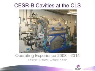
The ASTRID RF system • 105 MHz system • One cavity • Copper-plated Coaxial TEM cavity • 20 kW tube based (tetrode) FM transmitter • The bandwidth has been increased resulting in a lower maximum output (~8 kW) • Standard amplitude loop • Standard cavity tuning loop • Fast feedback loop • Which we are very dependent on
Combiner Atten- nuator Phase shifter -5 – -55 dB -150° – +40° The ASTRID RF system Rohde&Schwartz SMY01 104.95 MHz + phase modulation FM transmitter +36 dB, 10 kW PreAmp +40 dB, 10 W Fast feedback loop Amplitude loop Amplitude detector Manual or closed loop Splitter Cavity Tuning loop Phase comparison
Plunger and RF power during a fill RF power at Injection • Want low RF voltage at injection • Inject (pulsed) DC beam from microtron • Induce strong synchrotron oscillations => poor capture efficiency • Improved lifetime • Too high RF power => shorter bunch => increased Touschek scattering • Need enough RF power to overcome beamloading • Increase power as current increase • Finding the balance !
Fighting the beamloading • Fast Feedback Loop • Pickup the cavity voltage and feed it back to the cavity in opposite phase. • This way any beam induced voltage is counteracted • Problem: • Can only achieve perfect in opposition for one frequency • Needs to have a small group delay to have a large bandwidth
From amplitude loop +40 dB, 10 W +36 dB, 10 kW Combiner Atten- nuator Phase shifter -5 – -55 dB -150° – +40° Splitter To amplitude loop Fast Feedback Loop Principle Reference: A. Gamp, “Servo Control of RF Cavities under Beam Loading” CERN 92-03, 1992 F. Perez et.al., “Fast Feedback Loop for Beam Loading Compensation in the ANKA Booster” Proc. EPAC 2000, Vienna, Austria, p 1996
Cavity Voltage with Fast Loop Fast Feedback Loop OFF Fast Feedback Loop ON
Why is the Beam dropping out? • Good question, which we would very much like to know the answer to. • Is it because the Fast Loop is ringing, or is the ringing just because the detuning is so large when the beam drops out? • At lower Fast Feedback Gain, we see the beam drop-out without the fast loop ringing. • Why the large variation in forward and reverse power? • Is it a signature of the fast loop working, or is it a problem? • Could we get some warning?
Modulation of Forward Power • Just after a pulse from the microtron, we see a strong modulation on the forward (and reverse) power • We believe that the modulation is at the synchrotron frequency • The modulation periodgets longer with more current • We only see it with theFast Feedback Loop on • Partly induced by the kicker • Could be due to a small modulationof the cavity voltage (induced by thebeam), which is strongly amplifiedby the Fast Loop
Forward Power Variation • With Amplitude Loop off, we see a change in Forward Power when scanning the RF frequency across the cavity resonance • True or not? (crosstalk in the directional couplers?) • Properly due to back reflection from the transmitter due to lack of circulator • Problem or not? • Maybe increases the fast loop off resonance power
Conclusions • Shown you ASTRID and its RF system • Shown you our Fast Feedback Loop • Shown you some issues, which we believe are part of the limitations to the attainable current