RF Measurements: Techniques and Data
220 likes | 244 Vues
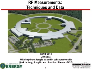
RF Measurements: Techniques and Data. CWRF 2010 Jim Rose With help from Hengjie Ma and in collaboration with Mark deJong, Song Hu and Jonathon Stampe of CLS. Original talk was to be “Experience with the RF Systems at NSLS-II. But as you can see we are not quite ready………. Outline.

RF Measurements: Techniques and Data
E N D
Presentation Transcript
RF Measurements:Techniques and Data CWRF 2010 Jim Rose With help from Hengjie Ma and in collaboration with Mark deJong, Song Hu and Jonathon Stampe of CLS
Original talk was to be “Experience with the RF Systems at NSLS-II But as you can see we are not quite ready………
Outline • Motivations • Traditional RF phase measurements on a seeded FEL RF system and on the Canadian Light Source • Measurements with Spectrum/dynamic spectrum analyzer • Mixer measurements with digital scope and post processing on the PC • Digital cavity controller based measurements • Summary
Motivations The NSLS-2 program has requirements of <0.15 degree phase jitter; need to characterize potential RF sources. • Solid state and IOT have better phase jitter performance than the klystron with its large cathode voltage-to-RF phase transfer function. Since the NSLS-2 is a virtual machine, we went to CLS to measure the klystron amplifier to quantify the phase jitter • Commitment: The other mother of invention. • ~9 years ago, while interviewing to change departments at BNL I was asked if I could measure jitter between a 100fs cathode driver/seed laser and the RF system to characterize and improve system- said yes even though I was not exactly sure how. This became the finger-pointing circuit to resolve arguments between RF and laser stability (we always won after this) I would like to begin by describing this latter circuit as an example of the accuracy of the mixer based phase measurement
Seeded-FEL Laser and S-Band LINAC RF system Laser/RF Phase Measurement Photo-cathode laser Seed laser Amplifier + tripler Bandpass filter 10 Hz traveling wave tank photo-cathode gun Klystron I/Q modulator 81.6 MHz CW LP filter preamp I/Q demodulator Ti:sapphire laser (not implemented) DSA 2856 MHz synthesizer 81.6MHz xtal Laser and RF synthesizer independently locked to Oscillator 2
Laser Room TsunamiLaser Oscillator GaAs photo-diode EOT Inc. ET-4000 81.6 MHz Comb HD21678 MiniCircuits TTE 315P-2856M-A Cage code 07766 F1237 ARRA 4194-10 ZJL-3G Hi-Q Bessel BP HD Communications Inc. +12 V Front Panel From LLRF Anaren 74125 To Pre-amp, DSA Rear panel To LLRF Scope to monitor zero-crossing SRS785 Dynamic Signal Analyzer SR560 Pre_amp Gain ~5-20 LP 30k-300k
Phase Jitter Measured between Laser Oscillator and RF Drive Each plot consists of histograms of 8 second duration of a mixer-based phase error measurement. Left plot is for laser oscillator and RF synthesizer driven from same crystal, on right laser output pulses are filtered to drive RF directly.In each plot the outside histograms are data taken by programming+/- 3 degree and +/- 2 degree steps, respectively, in the RF path for calibration. Side Note: shot to shot jitter from 40 MW klystron is ~150fs FWHM with 0.05% regulated charging PS
Don’t fix the jitter, join it: Laser-Driven and LINAC RF system Laser/RF Phase Measurement Photo-cathode laser Seed laser Bandpass filter traveling wave tank photo-cathode gun Klystron I/Q modulator I/Q demodulator Ti:sapphire/YaG laser DSA 81.6MHz xtal Worked well for this small class of experiments, with no downstream synchronization 2
Characterization of the CLS klystron transmitter • Part of a broader collaboration between CLS and NSLS-II on RF systems • NSLS-II must meet the <0.15 deg phase jitter specification: factor of ~3 beyond existing LS machines (I think)- past experience is no guarantee of future success. Decision to use the CLS system to determine whether klystron system can meet specification • Thanks to Mark deJong, Jonathon Stampe, Hengjie Ma, Nathan Towne and Song Hu for contributing to this work
Spectrum/Dynamic Signal AnalyzerData taken with Agilent 89441A DSA Transmitter forward power-Phase Cavity Field pickup- Phase Due to machine returning to normal operations measurements had to be taken closed loop, Cavity field response with 20 dB of gain in feedback masks effect of transmitter noise-transmitter forward power shows switching noise • Pro/Con of DSA: • High resolution, easy to configure • High dynamic range • Only one RF channel • Few points (3201 max in89441A) • Need to configure and calibrate TP
Traditional detector/mixer based RF measurements- Using Scope as digitizer Simple system with components costing a few hundred $ (even less € ) plus digital scope allows high resolution four channel correlated measurements
PSM modulated HV power supply switching lines and klystron RF phase Switching frequency of 100kHz over 86 switch modules creates sub-harmonics of ~ 1.2kHz This is a concern for NSLS2 since the synchrotron frequency is between 3-4 kHz Klystron HV Klystron RF out phase Although the harmonics are <-75dBc, they can be suppressed further by filtering with modest effort
Digital RF Controller for data measurement and analysis Example of NSLS-II controller GUI in MATLAB- 8 fast ADC channels with display, +history, + signal processing. Built in AM, FM modulation
Digital RF controllers as DSA Built in sweep features allows AM, PM and FM modulation of Reference input via feed-forward Transfer functions can be measured easily
Matlab processing allows power spectrum measurements online - 300kW-open loop into load
Digital controller as SA measuring Analog controller closed loop response Cavity field open and closed loop response: closed loop noise reduced- At cost of increased closed loop amplifier power
Open loop responseDigital Controller Cavity Voltage 2.4MV klystron power 72kW, no beam
Closed loop responseDigital Controller Cavity Voltage 2.4MV klystron power 72kW, no beam
Summary-Measurements • Traditional spectrum analyzer measurements can be complemented by mixer based measurements extended to four channels for correlation between PS HV and RF • These measurements can be built into digital RF controllers and displayed and put into history buffers for post-mortem • Digital controller based measurements are flexible, always online. No need to hook up equipment, calibration easier to keep correct
Summary- Switching PS/Klystron phase noise • Open loop measurements of klystron at full power shows switching harmonics at {switching frequency/#modules}- for CLS case these are within the synchrotron frequency band of the NSLS-II • Closed loop measurements show this noise to be reduced greater than 20db: within requirements. The 20 dB loop gain is not a fundamental limit, the firmware gain needs to be increased- we reached the end of the ‘knob’ • The PSM PS klystron transmitter can easily meet the NSLS-II requirements