HAM Radio Antennas
HAM Radio Antennas. KF7CLY Aug 2013. VHF/UHF. Antennas for the VHF and UHF bands are similar in many ways to HF antennas. The main differences are that VHF/UHF antennas are smaller and the losses caused by poor feed lines and elevated SWRs (or both) are more critical. .

HAM Radio Antennas
E N D
Presentation Transcript
HAM Radio Antennas KF7CLY Aug 2013
VHF/UHF • Antennas for the VHF and UHF bands are similar in many ways to HF antennas. The main differences are that VHF/UHF antennas are smaller and the losses caused by poor feed lines and elevated SWRs (or both) are more critical.
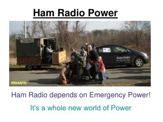
Omnidirectional Antennas • This type of VHF antenna transmits and receives in all directions at once (the same is true of the dipoles, loops and vertical antennas for HF use). All commonly used mobile antennas are omnidirectional. This makes sense because it is impractical to stop and point your car in the direction of the station you want to contact. Instead, the omnidirectional mobile antenna blasts your signal in all directions so that you’ll stand a decent chance of communicating no matter where you are driving.
Omnidirectional Antennas • Omnidirectional antennas are also found in base stations where the goal is to transmit and receive from any direction with minimal hassle and expense. Common omnidirectional antenna designs for base stations include ground planes, loops and J-poles, but there are others.
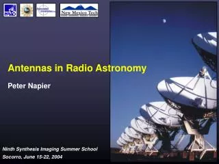
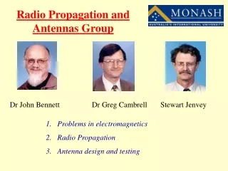
Omnidirectional Antennas Ground Plane J Pole
Omnidirectional Antennas Loop Loop
Omnidirectional Antennas • An omnidirectional antenna spreads your signal over a broad area, depending on how high you install it. Height is critical to the performance of all antennas at VHF and UHF frequencies. Higher is always better, whether that means putting the antenna on a flagpole, tower or a rooftop. If you are fortunate enough to operate from the summit of a hill or mountain where Mother Earth provides the altitude, that works, too.
Omnidirectional Antennas • If the advantage of an omni is that it radiates in all directions, that can be its disadvantage as well. An omnidirectional antenna can’t focus your reception or transmission. Once you put it in place, what you get is…well…what you get. There is little you can do to change it. If the station you’re talking to is west of your location, for example, all the power you are sending north, south and east is wasted. You will also receive signals--possibly interfering signals--from the same useless directions.
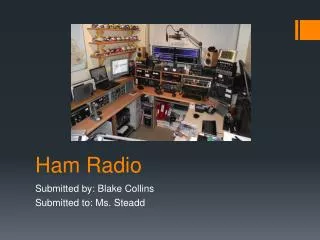
Directional Antennas • As the name implies, directional “beam” antennas focus your power and reception in a single direction. Just like HF antennas, directional VHF designs work by canceling the energy that radiates toward the back of the antenna and reinforcing the energy going toward the front. The result is a beam of RF power (and concentrated receive sensitivity) not unlike a searchlight or a magnifying glass.
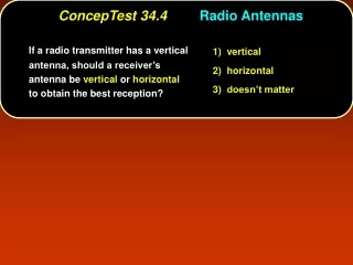
Directional Antennas • Directional antennas are ideal at VHF and UHF when you want maximum distance and minimum interference. They are almost mandatory for VHF DX work and satellite operating. Directional antennas also help tremendously on VHF FM when you’re trying to communicate with a distant station. Common directional antenna designs include the Yagi, quad and Moxon. Parabolic dish antennas—the kind you’ve likely seen for satellite TV reception—are also directional antennas.
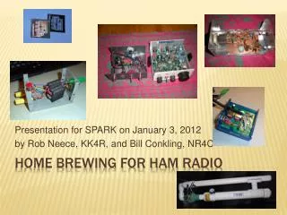
Directional Antennas Yagi Quad
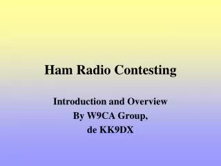
Directional Antennas Moxon Parabolic Dish
Directional Antennas • So what is the downside?
Directional Antennas • Directional antennas tend to be more complex and difficult to assemble. They can also be quite large in some configurations. For instance, a highly directional Yagi antenna for the 6-meter band, a model with 11 sections known as elements, can include a boom assembly that’s nearly 70 feet in length.
Directional Antennas • And what happens if your antenna is pointing north and the station you want to talk to is south? Unless you can turn your antenna, communication will be difficult or impossible. This is where the antenna rotator comes into play, just as it did for HF beam antennas. You may recall that a rotator is an electric motor that you install below your directional antenna. Its job is to turn your antenna to the direction you require.
Directional Antennas • Rotators add to the cost and complexity of a directional antenna system. A light duty rotator can cost about $100. If you need a heavy duty rotator to turn a bigger antenna (or more than one antenna), the cost can reach $500 or more. In addition to the hassle of stringing your feed line from the antenna back to your radio, you must also string a cable for the rotator. More wires equal more work, although the reward can be considerable!
Antennas for the HF Bands • The most powerful antennas for the HF bands or any band is the directional antenna, often referred to as the beam antenna. • When hams speak of beam antennas, they usually mean the venerable Yagiand quad designs. These antennas focus your signal in a particular direction (like a flashlight). Not only do they concentrate your transmitted signal, they allow you to focus your receive pattern as well. For example, if your beam is aimed west you won’t hear many signals from the east (off the “back” of the beam).
HF Bands • The problems with beam antenna systems are size and cost. HF beams for the lower bands are big antennas. At about 43 feet in width, the longest element of a 40-meter coil-loaded Yagi is wider than the wingspan of a Piper Cherokee airplane. • In terms of cost, a sizeable beam antenna and 75-foot crank-up tower will set you back at least $2,500. Then add about $500 for the antenna rotator, an electric motor that allows you to turn the antenna by remote control. On top of that, add the cost of cables, contractor fees (to plant the tower in the ground) and so on. In the end, you’ll rack up about $5,000.
HF Bands • If you have that much cash burning a hole in your pocket, by all means throw it at a beam antenna and tower. The rewards will be tremendous and you’ll never regret the investment. Between the signal-concentrating ability of the beam and the height advantage of the tower, you’ll have the world at your fingertips. Even a beam antenna mounted on a roof tripod can make your signal an RF juggernaut. • But do you need a beam and a tower to enjoy Amateur Radio? The issue isn’t whether they’re worthwhile (they are). The question is: Are they absolutely necessary? The answer, thankfully, is no.
HF Single-Band Dipoles • You can enjoy Amateur Radio on the HF bands with nothing more than a copper wire strung between two trees. This is the classic dipole antenna. It comes in several varieties, but they all function in essentially the same way. • Single-band dipoles are among the easiest antennas to build. All you need is some stranded, noninsulated copper wire and three plastic or ceramic insulators. A 1/2-wavelength dipole is made up of two pieces of wire, each 1/4-wavelength long.
Trap Dipoles and Parallel Dipoles • For multiband applications, you’ll often find the trap dipole and the parallel dipole. Traps are tuned circuits that act somewhat like automatically switched inductors or capacitors, adding or subtracting from the length of the antenna according to the frequency of your signal. The parallel dipole uses a different approach. In the parallel design, several dipoles are joined together in the center and fed with the same cable. The dipole that radiates the RF is the one that presents an impedance that most closely matches the cable (50 ohms). That matching impedance will change according to the frequency of the signal. One dipole will offer a 50-ohm match on, say, 40 meters, while another provides the best match on 20 meters. • Obviously, these designs are somewhat more complicated than single-band dipoles, although many hams do choose to build their own. If you don’t have time or desire to tackle a trap or parallel dipole, you’ll discover that many QST advertisers sell prebuilt models.
Random Length Multiband Dipole • You can also enjoy multiband performance without traps, coils, fans or other schemes. Simply cut two equal lengths of stranded copper wire. These are going to be the two halves of your dipole antenna. Don’t worry about the total length of the antenna. Just make it as long as possible. You won’t be trimming or adding wire to this dipole. • Feed the dipole in the center with 450-ohm ladder line (available from most ham dealers), and buy an antenna tuner with a balanced output. Feed the ladder line into your house, taking care to keep it from coming in contact with metal, and connect it to your tuner. Use regular coaxial cable between the antenna tuner and your radio.
Random Length Multiband Dipole • You can make this antenna yourself, or buy it premade if you’re short on time. A 130-foot dipole of this type should be usable on almost every HF band. Shorter versions will also work, but you may not be able to load them on every band. • Ladder line offers extremely low RF loss on HF frequencies, even when the SWR is relatively high. Just apply a signal at a low power level to the tuner and adjust the tuner controls until you achieve the lowest SWR reading. (Anything below 2:1 is fine.) You’ll probably find that you need to readjust the tuner when you change frequencies. (You’ll definitely need to readjust it when you change bands.)
Random Length Multiband Dipole • You may discover that you cannot achieve an acceptable SWR on some bands, no matter how much you adjust the tuner. Even so, this antenna is almost guaranteed to work well on several bands, despite the need to retune. • So why doesn’t everyone use the ladder line approach? The reason has much to do with convenience. Ladder line isn’t as easy to install as coax. You must keep it clear of large pieces of metal (a few inches at least). Unlike coax, you can’t bend and shape ladder line to accommodate your installation. And ladder line doesn’t tolerate repeated flexing as well as coaxial cable. After a year or two of playing tug o’ war with the wind, ladder line will often break.
Random Length Multiband Dipole • Besides, many hams don’t relish the idea of fiddling with an antenna tuner every time they change bands or frequencies. They enjoy the luxury of turning on the radio and jumping right on the air—without squinting at an antenna tuner’s SWR meter and twisting several knobs. • Even with all the hassles, you can’t beat a ladder-line fed dipole when it comes to sheer lack of complexity. Wire antennas fed with coaxial cable must be carefully trimmed to render the lowest SWR on each operating band. With a ladder line dipole, no pruning is necessary. You don’t even care how long it is. Simply throw it up in the air and let the tuner worry about providing a low SWR for the transceiver
Verticals • The vertical is a popular antenna among hams who lack the space for a beam or long wire antennas. In an electrical sense, a vertical is a dipole with half of its length buried in the ground or “mirrored” in its counterpoise system. Verticals are commonly installed at ground level, although you can also place a vertical on the roof of a building. • At first glance, a vertical looks like little more than a metal pole jutting skyward. A single-band vertical may be exactly that! However, if you look closer you’ll find a network of wires snaking away in all directions from the base of the antenna. In many instances, the wires are buried a few inches beneath the soil. These are the vertical’s radials. They provide the essential ground connection that creates the “other half” of the antenna. Multiband verticals use several traps or similar circuits to electrically change the length of the antenna according to the frequency of the transmitted signal. (The traps are in the vertical elements, not the radials.)
Verticals • Vertical antennas take little horizontal space, but they can be quite tall. Most are at least 1/4-wavelength long at the lowest frequency. To put this in perspective, an 80-meter full-sized vertical can be over 60 feet tall! Then there is the space required by all those radial wires. You don’t have to run the radials in straight lines. In fact, you don’t even have to run them underground. But you do need to install as many radials as possible for each band on which the antenna operates. Depending on the type of soil in your area, you may get away with a dozen radials, or you may have to install as many as 100. • Contemplate spending several days on your hands and knees pushing radial wires beneath the sod. It isn’t a pretty picture, is it? That’s why several antenna manufacturers developed verticals that do not use radials at all. The most efficient of these verticals are actually vertical dipoles. Yes, they are dipole antennas stood on end! There is no reason why this cannot be done. In fact, a vertical dipole can work quite well.
Verticals • So how does a traditional vertical antenna stack up against a traditional horizontal dipole when it comes to performance? If you have a generous radial system, the vertical can do at least as well as a dipole in many circumstances. Some claim that the vertical has a special advantage for DXing because it sends the RF away at a low angle to the horizon. Low radiation angles often mean longer paths as the signal bends through the ionosphere. • Without a decent radial system, however, the vertical is a poor cousin to the dipole. The old joke, “A vertical radiates equally poorly in all directions,” often applies when the ground connection is lacking, such as when the soil conductivity is poor. If you can’t lay down a spider web of radials, dipoles are often better choices.
Random Wires • A random wire is exactly that—a piece of wire that’s as long as you can possibly make it. One end of the wire attaches to a tree, pole or other support, preferably at a high point. The other end connects to the random-wire connector on a suitable antenna tuner. You apply a little RF and adjust the antenna tuner to achieve the lowest SWR. That’s about all there is to it. • Random-wire antennas seem incredibly simple, don’t they? The only catch is that your antenna tuner may not be able to find a match on every band. The shorter the wire, the fewer bands you’ll be able to use. And did you notice that the random wire connects directly to your antenna tuner? That’s right. You’re bringing the radiating portion of the antenna right into the room with you. If you’re running in the neighborhood of 100 W, you could find that your surroundings have become rather hot—RF hot, that is! We’re talking about painful “bites” from the metallic portions of your radio, perhaps even a burning sensation when you come in contact with the rig or anything attached to it.
Random Wires • Random wires are fine for low-power operating, however, especially in situations where you can’t set up a vertical, dipole or other outside antenna. And you may be able to get away with higher power levels if your antenna tuner is connected to a good Earth ground. (A random-wire antenna needs a good ground regardless of how much power you’re running.) If your radio room is in the basement or on the first floor, you may be able to use a cold water pipe or utility ground. On higher floors you’ll need a counterpoise. • A counterpoise is simply a long, insulated wire that attaches to the ground connection on your antenna tuner. The best counterpoise is 1/4-wavelength at the lowest frequency you intend to use. That’s a lot of wire at, say, 3.5 MHz, but you can loop the wire around the room and hide it from view. The counterpoise acts as the other “terminal” of your antenna system, effectively balancing it from an electrical standpoint.
Indoor Antennas • So you say that you can’t put up an outdoor HF antenna of any kind? There’s hope for you yet. Antennas generally perform best when they’re out in the clear, but there is no law that says you can’t use an outdoor antenna indoors. • If you have some sort of attic in your home, apartment or condo, you’re in luck. Attics are great locations for indoor antennas. For example, you can install a wire dipole in almost any attic space. Don’t worry if you lack the room to run the dipole in a straight line. Bend the wires as much as necessary to make the dipole fit into the available space.
Indoor Antennas • Of course, this unorthodox installation will probably require you to spend some time trimming and tweaking the length of the antenna to achieve the lowest SWR (anything below 2:1 is fine). Not only will the antenna behave oddly because of the folding, it will probably interact with nearby electrical wiring. • Ladder-line fed dipoles are ideal for attic use—assuming that you can route the ladder line to your radio without too much metal contact. In the case of the ladder-line dipole, just make it as long as possible and stuff it into your attic any way you can. Let your antenna tuner worry about getting the best SWR out of this system
Indoor Antennas • The same dipoles and loops that you use in your attic can also be used in any other room in your home. The same techniques apply. Keep the antenna as high off the floor as possible. (As with most antennas, the more height, the better.) For indoor operating, however, most hams recommend using low output power. You’ll avoid RF “bites” as well as interference to VCRs, TVs and so on. Many hams have been successful operating indoor antennas with just a few watts output.