Download
1 / 119
1.23k likes | 1.27k Vues
This presentation offers a practical understanding of amateur radio antennas without overwhelming technical jargon. Ideal for new hams, it covers VHF/UHF antennas used in emergencies and repeater communication, with minimal math. Learn why antennas are crucial in radios and explore various antenna types. Discover the importance of antennas for effective radio communication and tips on choosing the right antenna. Gain insights into antenna design, operation, and common characteristics like efficiency and bandwidth.

E N D
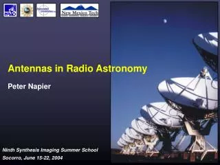
Understanding Antennas A Simplified Perspective for Ham Radio Operators Jim Peisker AF5NP 25 February 2016
What to Expect This presentation provides a working understanding of amateur radio antennas without being overly technical or dry. Some mathematics and basic physics are required to properly understand antenna operation but this will be minimized. The target audience here are newer hams with limited knowledge of antennas. It is presented at the Technician license level. You will see Technician license exam questions and answers to refresh your knowledge.
What to Expect While antenna theory works for all frequencies and types of construction, the emphasis here is on VHF/UHF antennas used for emergency communication and repeater use. This is because most new hams get started with local (short-range) radio equipment. Other antennas are discussed, however, and the information provided is useful for all antennas types and frequencies.
Disclaimer The author is not an antenna expert. Information presented here is from many different sources and represents that which the author considers most reliable and useful.
Why Understand Antennas? The antenna is arguably the most important component in most radio systems. Let’s use a sound system analogy to help reinforce this notion. With a home audio system, you can have a $10,000 amplifier with small, cheap loudspeakers and it will sound awful. Conversely, with a basic cheap audio amp and some really good speakers it can sound fabulous. The speakers make all the difference; they contribute the most to what we hear.
Why Understand Antennas? The same goes for an amateur radio station. Here we can have the nicest transceiver you can buy paired with a lousy antenna and you won’t hear much or be heard well. But take a cheap radio with a good antenna and you can do wonders. The antenna makes the most impact on a radio communications system. Whether transmitting or receiving, a weak signal isn’t usually due to poor band conditions or lack of power, it’s more likely caused by a bad antenna.
Why Understand Antennas? You may hear old-time hams say something like, “Spend twice as much on your antenna as you do on your radio.” That’s not practical advice--considering the relative costs of the two--but generally good guidance that we should pay more attention to the quality of our antenna than we do our fancy radio equipment. Because the antenna is so important in radio, it is essential that we understand the basics of these devices.
Definition An antenna is simply defined as an arrangement of conductors used to radiate electromagnetic (E-M) energy into space (the air) or, conversely, for collecting it from space. Antenna Schematic Symbol Sounds simple, right? In reality, functional antennas are a bit more complicated. There are many factors to consider in practical antenna design. We’ll look at most of them here.
Definition It may also be helpful to think of an antenna as a transducer which converts alternating current (AC) into radio waves, and, conversely, radio waves into AC. You may be unfamiliar with the word transducer but you already know what they are. A transducer is a device which changes one form of energy into another. We are all familiar with the following: speakers, microphones, temperature and pressure sensors, room lighting of all sorts, and indicators. We use these every day and they are all transducers. We control the electrical side of things in our radios and the antenna converts that AC into useful radio waves, and vice-versa.
Antenna Varieties There are dozens of different antenna designs and they all have their place in radio. Antennas used in emergency communications (EmComm) are mostly VHF/UHF vertical whips but you should be familiar with the more common antenna configurations used at all frequencies. These are shown later in the presentation. Until then we’ll look at some basic features and details of all antennas.
Topics Even a basic understanding of antennas requires discussion of a number of topics. We will briefly touch on these: Additionally we will cover practical detail such as antenna types, configurations, safety, and the peculiarities and limitations of VHF/UHF mobile and hand-held antennas. • Reciprocity • Directivity & Gain • Polarization • Impedance • Wavelength • Resonance • E-M Radiation • Physical Length • The Dipole • Efficiency • Bandwidth • Real-World Antennas
Common Characteristics • Antennas come in a myriad of sizes, shapes and configurations. These vary greatly based on the nature of the application (mainly frequency and performance). • Regardless of these differences, all antennas share three common characteristics: • Reciprocity • Directivity & Gain • Polarization
Reciprocity Reciprocity means it works both ways. The electro-magnetic characteristics of an antenna make it work equally well for transmitting and receiving. This means that for both transmission and reception, antennas are equally directive, have equal gain and bandwidth, and have the same polarity.
Reciprocity Sure, when transmitting it usually involves watts or tens of watts or hundreds of watts of power. And when receiving an antenna is dealing with thousandths of a watt (mW) or millionths of a watt (μW) or even less. But the laws of physics don’t distinguish between big watts and little watts; it’s still power transfer and energy conversion at issue in an antenna. Reciprocity works for power as well.
Reciprocity The practical result of reciprocity is that the same antenna is almost always used for both transmitting and receiving. This is where that transmit-receive (TR) switch comes into play in your transceiver. Not that it has to be this way; occasionally a different receiving antenna is used. In this case it often involves a separate receiver with a high-performance receiving antenna.
Directivity & Gain Directivity is an antenna’s ability to focus the energy to—or from—one or more directions. All practical antennas have some degree of directivity, some slightly directive (verticals), some semi-directional (dipole), and others very directional (beam). Only the theoretical isotropic antenna is truly omni-directional. T9A01-2014: What is a beam antenna? An antenna that concentrates signals in one direction T9A06-2014: What type of antennas are the quad, Yagi, and dish? Directional antennas
Directivity & Gain Directivity of an antenna is best understood by viewing its radiation pattern graphically. Antennas have radiation patterns viewed from above (azimuth) and viewed from the side (elevation). Both may be of interest to the user. Vertical Monopole Azimuth Vertical Monopole Elevation Vertical Monopole 3-D
Directivity & Gain More antenna radiation patterns. Yagi Azimuth Dipole Azimuth Yagi Elevation Parabolic (Dish) Azimuth
Directivity & Gain While gain is directly related to directivity, it is more specifically a measure of the increase in signal in certain directions relative to a reference antenna. So directivity is the quality of an antenna to focus radio waves and gain is the measurement of it. T9A11-2014: What is meant by the gain of an antenna? The increase in signal strength in a specified direction when compared to a reference antenna
Polarization Recall that radio waves consist of both electric and magnetic fields oscillating at right angles to each other. E=Electric Field B=Magnetic Field T3A07-2014: What type of wave carries radio signals between transmitting and receiving stations? Electromagnetic T3B03-2014: What are the two components of a radio wave? Electric and magnetic fields Animation of E-M wave
Polarization Antenna polarization is determined by the orientation of the electric field with respect to the earth. T3B02-2014: What property of a radio wave is used to describe its polarization? The orientation of the electric field
Polarization Generally speaking, since the electric field is oriented parallel to the conductor, the orientation of the radiating conductor is also its polarization. A vertical antenna is vertically polarized. A horizontal antenna is horizontally polarized. An angled or bent antenna is partially polarized in both orientations. T9A02-2014: Which of the following is true regarding vertical antennas? The electric field is perpendicular to the Earth
Polarization For line-of-sight communications in the VHF and UHF spectrum, antenna polarization is important. All repeater antennas and mobile antennas are (or should be) vertically polarized. Handheld transceivers (HTs) work best when held with the antenna up and down. You would see about 3dB signal loss (half power) at a 45º tilt. For short distances in open space polarization is a non-issue due to relative signal strength. T3A04-2014: What can happen if the antennas at opposite ends of a VHF or UHF line of sight radio link are not using the same polarization? Signals could be significantly weaker
Polarization At lower frequencies in the HF spectrum antenna orientation is less important because ionospheric propagation randomizes polarization. This blended E-field orientation is sometimes referred to as elliptical polarization. As a result, you can use either vertical or horizontal antennas on HF bands. T9A03-2014: Which of the following describes a simple dipole mounted so the conductor is parallel to the Earth's surface? A horizontally polarized antenna T3A09-2014: Which of the following results from the fact that skip signals refracted from the ionosphere are elliptically polarized? Either vertically or horizontally polarized antennas may be used for transmission or reception
Other Factors OK, so we’ve reviewed the three properties common to all antenna types: Reciprocity, Directivity & Gain, and Polarization. Hope you’re still with us at this point. Now let’s explore other factors important to antenna theory. These start to get a little more complex but we’ll keep it as simple as practical.
Impedance As you may recall, impedance is the sum of the DC resistance plus the inductive and capacitive reactance at a given frequency [ Z=R+jX ]. In loose terms, it can be considered “AC resistance”. Reactance varies with AC frequency. Inductive reactance increases with frequency [ XL=2πfL ]. Capacitive reactance decreases [ XC=1/(2πfC) ]. All conductors have some measurable inductance and capacitance in relation to earth and other conductors. T5C12-2014: What is meant by the term impedance? It is a measure of the opposition to AC current flow in a circuit
Impedance This means that all antennas have impedance at a given frequency. Antenna impedance varies with conductor arrangement, signal frequency, height above ground, conductor diameter, nearby objects, and connecting wires (feedline), among other things. For maximum power transfer of a source to a load, the impedance of the source, load and transmission line must be the same (matched). ~ Signal Source Load Transmission Line
Impedance In an antenna system these three impedances are matched as closely as possible over a specified range of frequencies. When there is an impedance mismatch, some of the signal is reflected back to the source. Of course, the impedance there doesn’t match so part of the reflected signal is reflected back again. And so on: back and forth until the signal is attenuated into oblivion, losing part of its energy all the way. So you see how power is lost with a mismatch.
Impedance Matching antenna impedance seems obvious when transmitting, since you want all of your transmitter power to be radiated from the antenna. But it also works in reverse (reciprocity). When receiving, signal strength is also maximized by properly matched impedances. Most modern ham radio equipment has a 50Ω characteristic impedance. The cable may or may not be 50Ω. The antenna itself rarely is 50Ω. T5C13-2014: What are the units of impedance? Ohms
Impedance To match the impedance of the radio to the transmission line and antenna, various means may be employed. Some are used at the radio, some at the antenna. We will not go into detail here; just be aware that hams use a variety of impedance matching techniques. So we see that impedance matching is important for maximum power transfer when transmitting and receiving radio signals T9B01-2014: Why is it important to have a low SWR in an antenna system that uses coaxial cable feed line? To allow the efficient transfer of power and reduce losses
Impedance A common way for hams to quantify impedance matching is with the term Standing Wave Ratio (SWR). SWR is a generalized measurement of how well matched the radio is to the antenna and feedline. SWR is quite a topic in and of itself, and is more associated with the transmission line. The antenna is only one contributor to the subject so we will leave it at that in this presentation. T7C03-2014: What, in general terms, is standing wave ratio (SWR)? A measure of how well a load is matched to a transmission line
Wavelength Let’s review the concept of wavelength because it is fundamental to antenna behavior and design. At any frequency it takes a certain amount of time for a wave to complete one cycle. A cycle is any repeating feature of the waveform. Radio waves have sinusoidal form. Cycle Amplitude Time Cycle Frequency = How many cycles per second (Hz) # Cycles 1 Second =Hz
Wavelength Because the wave moves over time (very fast!), it travels a certain distance in any given period. Wavelength is the distance a wave travels in one complete cycle. We measure this in meters. λ Amplitude Wavelength is represented by the Greek letter Lambda (λ) λ Distance λ T3B01-2014: What is the name for the distance a radio wave travels during one complete cycle? Wavelength
Wavelength Viewed in 3D animation, it’s not only cool to look at, but may help us understand it a little better. Constant wavelength (λ) shown moving in this area. The red and blue sine waves are the electricand magnetic fields oscillating at right angles to each other at the radio frequency. Radio wave is propagating this way at ~ the speed of light.
Wavelength Radio waves are typically oscillating millions of times per second (MHz). They are traveling near the speed of light (300 million meters per second). The time it takes for a radio wave to complete one cycle equals the speed of light (approximately) divided by the radio frequency. 300M m/sec RF Hz
Wavelength Simplifying the math shows us that to calculate wavelength, we simply divide 300 by the frequency in MHz. The millions (Megas) cancel each other out. So wavelength at the center of our most common VHF radio band would be: 300/146=2.05m Hey, that’s our 2-meter band! At the center of our popular UHF band the wavelength would be: 300/435=0.69m We call this 0.7m (700mm) wavelength the 70cm band.
Wavelength So we see that higher frequencies complete one cycle in less time than lower frequencies. This means that the wavelength of higher frequencies is shorter than that of lower frequencies. Frequency and wavelength are inversely proportional. Shorter λ Longer λ Lower Frequency Higher Frequency T3B05-2014: How does the wavelength of a radio wave relate to its frequency? The wavelength gets shorter as the frequency increases
Resonance Antenna resonance involves reflecting RF waveforms which are reinforced by recurring signals. Analogous to that sympathetic ringing condition we hear in a guitar string tuned to a particular note. This situation occurs when the antenna conductors are at one half wavelength in dimension. Graphics on the following slides will help to explain this concept.
Resonance This demonstration uses a single wire antenna that is exactly one half wavelength (λ/2) long at the resonant frequency. We apply a RF waveform to end A. The signal travels down to the wire to point B. ~ ~ RF Source ~ B A λ/2 Antenna Wire
Resonance At point B the wave sees an open circuit at the end of the wire and so it reflects back towards the source at point A. This reflection is 180º out of phase with the original signal. That is, its sine wave polarity is flipped. ~ ~ RF Source ~ B A λ/2 Antenna Wire
Resonance When the reflected wave arrives back at point A it is once again reflected back to point B. This reflection again inverts the polarity of the wave and so it goes back to 360º (or 0º). ~ ~ RF Source B A λ/2 Antenna Wire
Resonance Due to perfect timing with a half-wave wire length, a new wave is generated from the signal source which is exactly in phase. So now we have the reflected energy from the previous cycle adding to the new energy of the next cycle. This additive effect is positive but not double, due to losses (resistance) in the wire. ~ ~ RF Source B A λ/2 Antenna Wire ~
Resonance Synchronized at resonance, the waves reinforce each other while traveling back and forth on the antenna wire. The resulting flow of electrons is maximized and more energy is converted from RF to E-M (or vice-versa). This happens on half-wavelength wires (and odd multiples). Recurring Wave Reflected Wave Composite Wave Net Gain
Resonance At resonance the antenna elements achieve maximum in-phase current which improves its performance in transmission and reception. The further the waveform deviates from the resonant frequency, the less supportive the reflective waves become. In fact, at 180º reflection (antiresonance), the waves cancel and most antenna energy is lost. Recurring Wave Reflected Wave Composite Wave Net Zero
Resonance An antenna need not be perfectly resonant to work well, but it works best at resonance. This sympathetic reinforcement phenomenon on half-wavelength wires forms what is called a standing wave pattern as shown in the animation below. Standing waves are a key attribute of resonance.
Resonance To help visualize resonance, impedance and standing waves, there is an outstanding video located at: https://www.youtube.com/watch?v=DovunOxlY1k The video presentation is very old (1961) but there is nothing else quite like it. It is expertly presented and very interesting and quite applicable to understanding antenna waves. Highly recommended for all hams to spend a half hour watching this video on the Similarities of Wave Behavior from the AT&T archives.
Resonance There is another kind of resonance you may hear about that involves the interaction of capacitive and inductive reactance in an antenna. However, wave resonance is by far the dominant factor in most antennas so we will only mention reactive resonance in passing.
E-M Radiation We understand that radio waves are made of oscillating electric and magnetic fields, but what makes antennas radiate or capture them? OK, not really magic, but it is complex. This is where we avoid some highly technical discussion. You just have to know that accelerating electrons cause an E-M field to radiate (transmit a radio wave). Also accept that an E-M field causes electrons to accelerate in a conductor (receive a radio wave).
E-M Radiation At radio frequencies, electrons in the antenna’s conductor are oscillating rapidly in nearly-continuous acceleration. This acceleration causes E-M radiation from the antenna at that frequency. This is what the antenna does as a transducer. If you really want to dive into the technical details, study up on Maxwell’s equations, Faraday’s Law and electrodynamics.
E-M Radiation All conductors radiate E-M waves to some degree or another. This varies by many factors, mainly signal frequency and conductor characteristics. Antennas are conductors designed specifically to radiate or capture radio waves at certain frequencies. You might say that all other conductors are unintentional antennas. Their behavior can often be ignored, but sometimes they contribute to radio frequency interference (RFI) problems.