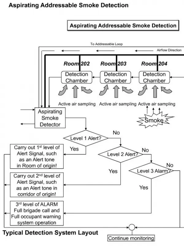
CF3000 Addressable Fire Detection System
CF3000 Addressable Fire Detection System. Introduction. History JSB and Menvier Acquired by Cooper Industries ~1999 / 2000 Analogue Addressable CF3000 range Started development approx 2004 Rationalisation of the legacy technology into one new platform


CF3000 Addressable Fire Detection System
E N D
Presentation Transcript
CF3000 Addressable Fire Detection System
Introduction History • JSB and Menvier • Acquired by Cooper Industries ~1999 / 2000 • Analogue Addressable CF3000 range • Started development approx 2004 • Rationalisation of the legacy technology into one new platform • To develop an entire single-manufacturer range • Includes CF3000, DF6000, FX6000 • Fire Detection • Voice Evacuation, • Emergency Voice Communication Systems
Introduction Agenda • Introduction • Concept of Operation • Control Panels • Addressable Devices • Networking • Operation, Commissioning and Fault Finding
Introduction Range • CF3000: • 1 – 4 loops per panel • 200 devices per loop • 504 loops max per 126 panel network • CF1100/1200: • 1 – 2 loops per panel • 200 devices per loop • 252 loops max per 126 panel network 1-4LP: CF3000 / DF6000 / FX6000 1LP: CF1100 / DF6100 / FX6100 2LP: CF1200 / DF6200 / FX6200
Introduction Key Features • UL and EN54 Certification • 1, 2 or 4 loops per panel • 200 addresses per loop • Max 512 detection devices per panel for EN54 • Recommended 150 devices per loop for practical application • Software Allocated Addressing • Optional hard addressing via CF800PROG • Network up to 126 panels • (504 or 252 max) • 96 Zone LED indication • 250 Zones per panel in configuration software
Introduction System Schematic ADDRESSABLE SPUR CIRCUIT LOOP 1 ADRRESSABLE LOOP CONVENTIONAL SOUNDERS ~ ~ CONVENTIONAL SOUNDERS LOOPS 2-4 SITE MONITOR SYSTEM SITE GRAPHICS SYSTEM MODBUS OUTPUT TO BMS SYSTEM BACNET OUTPUT TO BMS SYSTEM ~ ~ ~ CF3000 CW9000 CTPR3000 EC700 EC200 ECO232 ECO232 EC650 EXT 24V EXT 24V CFSFL01 LON-FO NC NC NC FIBRE OPTIC UP TO MAX 126 NETWORK NODES ~ ~ LOCAL AREA NETWORK EXT 24V NC NC EC400 EC400 EC540 CF1100/1200 CF3000
Concept of Operation Autolearn • Complete interrogation and reallocation of loop devices, addresses and config • Soft Address: in loop order, spurs first then ongoing loop • Hard Address: pre-programmed with CF800PROG Replace Device • Direct replacement of an existing device on an operational system Delete Device • Removing an existing device from an operational system Add Device • Adding a new device to an operational system Check Auto Config • Loop connectivity check • Loop status interrogation and fault reporting Intermittent Fault Search • Reduces fault tolerance to identify any corrupted/intermittent devices
Concept of Operation Autolearn • Complete interrogation and reallocation of loop devices, addresses and config • Start with loop return disconnnected
Concept of Operation 001 Panel>>>> All isolators O/C
Concept of Operation • 002 Panel>>>> Request device type 001 Panel>>>> All isolators O/C
Concept of Operation • 003 Device>>> Device type = Sounder • 002 Panel>>>> Request device type 001 Panel>>>> All isolators O/C
Concept of Operation • 004 Panel>>>> Request device status • 003 Device>>> Device type = Sounder • 002 Panel>>>> Request device type 001 Panel>>>> All isolators O/C
Concept of Operation • 005 Device>>> Status = OK • 004 Panel>>>> Request device status • 003 Device>>> Device type = Sounder • 002 Panel>>>> Request device type 001 Panel>>>> All isolators O/C
Concept of Operation • 006 Panel>>>> Request device address • 005 Device>>> Status = OK • 004 Panel>>>> Request device status • 003 Device>>> Device type = Sounder • 002 Panel>>>> Request device type 001 Panel>>>> All isolators O/C
Concept of Operation • 007 Device>>> Address = 254??? • 006 Panel>>>> Request device address • 005 Device>>> Status = OK • 004 Panel>>>> Request device status • 003 Device>>> Device type = Sounder • 002 Panel>>>> Request device type
Concept of Operation • 008 Panel>>>> New address = 001 • 007 Device>>> Address = 254 • 006 Panel>>>> Request device address • 005 Device>>> Status = OK • 004 Panel>>>> Request device status • 003 Device>>> Device type = Sounder • 1
Concept of Operation • 009 Panel>>>> Close isolator • 008 Panel>>>> New address = 001 • 007 Device>>> Address = 254 • 006 Panel>>>> Request device address • 005 Device>>> Status = OK • 004 Panel>>>> Request device status • 1
Concept of Operation • 010 Panel>>>> Request device type • 009 Panel>>>> Close isolator • 008 Panel>>>> New address = 001 • 007 Device>>> Address = 254 • 006 Panel>>>> Request device address • 005 Device>>> Status = OK • 1
Concept of Operation • 011 Device>>> Device type = Optical Detector • 010 Panel>>>> Request device type • 009 Panel>>>> Close isolator • 008 Panel>>>> New address = 001 • 007 Device>>> Address = 254 • 006 Panel>>>> Request device address • 1
Concept of Operation • 012 Panel>>>> Request device status • 011 Device>>> Device type = Optical Detector • 010 Panel>>>> Request device type • 009 Panel>>>> Close isolator • 008 Panel>>>> New address = 001 • 007 Device>>> Address = 254 • 1
Concept of Operation • 013 Device>>> Status = OK, Analogue value = 20??? • 012 Panel>>>> Request device status • 011 Device>>> Device type = Optical Detector • 010 Panel>>>> Request device type • 009 Panel>>>> Close isolator • 008 Panel>>>> New address = 001 • 1
Concept of Operation • 014 Panel>>>> Request device address • 013 Device>>> Status = OK • 012 Panel>>>> Request device status • 011 Device>>> Device type = Optical Detector • 010 Panel>>>> Request device type • 009 Panel>>>> Close isolator • 1
Concept of Operation • 015 Device>>> Address = 254??? • 014 Panel>>>> Request device address • 013 Device>>> Status = OK • 012 Panel>>>> Request device status • 011 Device>>> Device type = Optical Detector • 010 Panel>>>> Request device type • 1
Concept of Operation • 016 Panel>>>> New address = 002 • 015 Device>>> Address = 254 • 014 Panel>>>> Request device address • 013 Device>>> Status = OK • 012 Panel>>>> Request device status • 011 Device>>> Device type = Optical Detector • 2 • 1
Concept of Operation 017 Panel>>>> Close isolator 016 Panel>>>> New address = 002 015 Device>>> Address = 254 014 Panel>>>> Request device address 013 Device>>> Status = OK 012 Panel>>>> Request device status • 2 • 1
Concept of Operation • Repeated for next device, • 3 • 2 • 1
Concept of Operation • Etc, • 3 • 4 • 2 • 1
Concept of Operation • Etc, • 3 • 4 • 5,6 • 2 • 1
Concept of Operation • Etc, • 3 • 4 • 5,6 • 2 • 7 • 1
Concept of Operation • Etc, • 3 • 4 • 5,6 • 2 • 7 • 1 • 8
Concept of Operation • Etc, until all devices identified • 3 • 4 • 5,6 • 2 • 7 • 1 • 9,10 • 8
Concept of Operation • Re-connect loop return cable • 3 • 4 • 5,6 • 2 • 7 • 1 • 9,10 • 8
Concept of Operation Autolearn with Spur Circuits • when spur isolators are encountered on the loop, the spur circuit is addressed first, then the loop addressing is continued • 3 • 4 • 5 • 5,6 • 9 • 7 • 8 • 2 • 1
Concept of Operation Autolearn with Spur Circuits • Spur isolators have no address or communications capability • 3 • 4 • 5,6 • 9 • 7 • 8 • 2 • 10 • 1 • 11 • 12,13 • 14
Concept of Operation Autolearn with Spur Circuits • The last device must have an address, ie, it cannot be a spur isolator • 3 • 4 • 5,6 • 9 • 7 • 8 • 2 • 10 • 1 • 16,17 • 15 • 11 • 12,13 • 14
Concept of Operation Replace Device • Direct replacement of an existing device on an operational system • Replacement with the same device type only • ONE by ONE • 3 • 4 • 5 • 2 • 6 • 254 • OLD • NEW • 1 • 8 • 7
Concept of Operation Replace Device • Physically replace the device with a new one (default address 254) • 3 • 4 • 5 • 2 • 254 • 6 • NEW • OLD • 1 • 8 • 7
Concept of Operation Replace Device • Then select Replace Device option at Control Panel • Replacement device is identified and address reallocated • Discard old device • 3 • 4 • 5 • 2 • 6 • 6 • DISCARD • NEW • OLD • 1 • 8 • 7
Concept of Operation Add Device • Add a new device to an operational system • ONE by ONE • 3 • 4 • 5 • 2 • 254 • NEW • 1 • 7 • 6
Concept of Operation Add Device • Physically add the new device (default address 254) • Then select Add Device option at panel • New device identified and the lowest unused address allocated • 3 • 4 • 5 • 2 • 8 • 254 • NEW • 1 • 7 • 6
Concept of Operation Add Device • Allocate the device to a zone • Enter the device description text • Allocate any relevant device settings • 3 • 4 • 5 • 2 • 8 • NEW • 1 • 7 • 6
Concept of Operation Delete Device • Removing an existing device from an operational system • ONE by ONE • Do not delete Loop 1 Device 1 • 3 • 4 • 5 • 2 • 6 • 1 • 8 • 7
Concept of Operation Delete Device • Select Delete Device option at panel • Then physically remove device (address returned to default 254) • 3 • 4 • 5 • 2 • 254 • 1 • 8 • 7
Control Panels Standby Power • Integrated Power Supply Unit • Loop and Standby Calculator inbuilt in Site Installer software • CF3000 • Standard Housing 24V 12Ah capacity • Deep Housing 24V 24Ah capacity • CF1100/1200 • Standard Housing 24V 7Ah capacity
Control Panels Optional Protective Cover • Suitable for CF3000 • Lockable clear cover • Prevents unauthorised access • Inbuilt SCROLL and MUTE BUZZER buttons • May be retro-fitted at a later date • Use with ‘Screen Cover’ menu mode
Control Panels Optional Integral Printer • Suitable for CF3000 • Lockable printer door • Self loading ‘Drop-In’ paper cradle • Removable blanking plug for retro-fit
Control Panels Circuit Connections • CF3000 12V 24V 24V
Control Panels Circuit Connections • CF1100 / CF1200 12V START LOOP END LOOP
Control Panels False Alarm Reduction: Alarm Investigation Delay • T1/T2 timers • User acknowledgment of alarm condition • Allows a further investigation time • 1: Acknowledgement Delay • 3 minutes max • All outputs or FRE only are delayed • 2: Investigation Delay • 10 minutes max • Full activation at end of delay • Activates according to programmed settings
Control Panels • False Alarm Reduction: Alarm Verification Delay • Filter out transient alarms • Reduces disruption from nuisance alarms • Select zones as required • 1: Verification Stage • EN: 15 or 30 seconds verification delay • UL: 60 seconds verification delay • 2: Full Alarm • Full activation if smoke remains at end of delay • Activates according to programmed settings