
Tasks
Tasks. Simulation of Antenna Placement on Aircraft Determine whether to use HFSS or FEKO Compare FEKO and HFSS antenna models Create simplified simulation models of antenna on aircraft Build up to Full Antenna on free aircraft model Acquire more accurate 3D model of chose aircraft

Tasks
E N D
Presentation Transcript
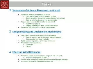
Tasks • Simulation of Antenna Placement on Aircraft • Determine whether to use HFSS or FEKO • Compare FEKO and HFSS antenna models • Create simplified simulation models of antenna on aircraft • Build up to Full Antenna on free aircraft model • Acquire more accurate 3D model of chose aircraft • Twin Otter or Bassler • Simplify geometry for more efficient simulations • Determine optimal location for antenna placement • Design Feeding and Deployment Mechanisms • Design/Acquire Telescopic deployment mechanism • Choose weather and temperature resistant material • Electric motor and other methods • Match antenna impedance to RF input of receiver • Antenna monitoring systems • Thermistor • Camera • Effects of Wind Resistance • Determine effects of wind for speed ranges of 120-115 knots • Possible faster speeds as well • Choose most resilient materials for antenna and telescopic structure • Simulation of the antenna and structures in full.
Antenna Simulation: FEKO vs. HFSS Frequency: 0.5 - 2.0 GHz @ 0.1 GHz Steps Realized Gain FEKO Base Dia = 7.2 in Height = 36 in 30 Turns GND Dia = 12 in Realized Gain HFSS 3dB BW ~64° Base Dia = 7.2 in Height = 36 in 30 Turns GND Dia = 12 in
Near-Field Plots Frequency: 2 GHz HFSS FEKO
Near-Field Plots FEKO HFSS Frequency: 0.5 GHz
Input Impedance FEKO HFSS Real Imaginary
Antenna Placement Determination Free Aircraft Model • Simulate Antenna on Aircraft Fuselage • Utilized free model to obtain approximate results • Determine whether HFSS or FEKO is more useful (FEKO model is not yet resolved) • Simulation time • Memory • Accuracy Underside Fuselage Antenna
Deployment and Feeding Expanding Antenna • Low Cross-section telescoping structure • Also consider a fixed-length pivot/tilting mechanism • Depending on chosen aircraft • Minimum Collapse Depth • Number of stages • Material to be used • Cold resilience • Wind resistive • Deploying Motor • Will consider manual deployment • Additional antenna support structures • Maintain Antenna wire spacing • Prevent mechanical resonance • Mount to aircraft fuselage • Match 50 Ohm input to 300 Ohm Antenna Impedance Example of pneumatic telescoping cylinder