15-08-0044-00-004e
200 likes | 362 Vues
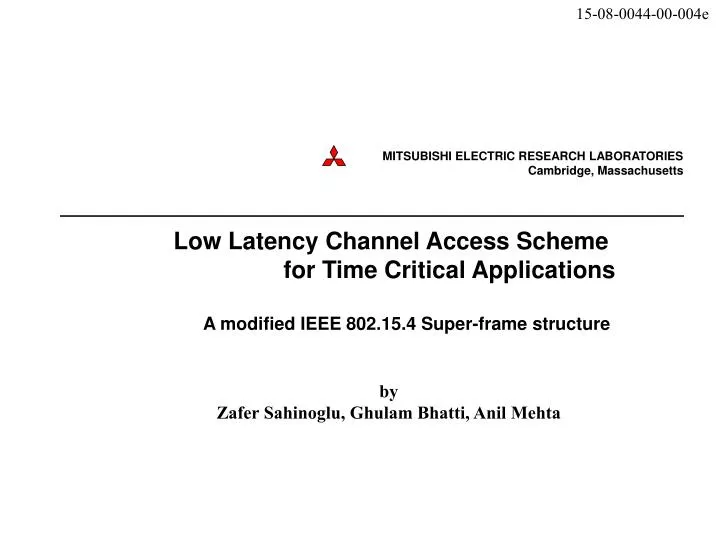
15-08-0044-00-004e. Low Latency Channel Access Scheme for Time Critical Applications A modified IEEE 802.15.4 Super-frame structure. by Zafer Sahinoglu, Ghulam Bhatti, Anil Mehta. 15-08-0044-00-004e. Ultra-reliable Wireless Network. Motivation

15-08-0044-00-004e
E N D
Presentation Transcript
15-08-0044-00-004e Low Latency Channel Access Scheme for Time Critical ApplicationsA modified IEEE 802.15.4 Super-frame structure by Zafer Sahinoglu, Ghulam Bhatti, Anil Mehta
15-08-0044-00-004e Ultra-reliable Wireless Network • Motivation • Current IEEE 802.15.4 Channel Access Scheme (CAS) • Improved CAS Approach • Simulation settings • Simulation results – latency and reliability • Theoretical validation • Future work
Current IEEE 802.15.4 Channel Access Scheme (CAS) beacon Superframe interval beacon Beacon interval GTS Inactive CFP CAP CAP GTS GTS GTS ~= Beacon Interval DATA ACK This is latency only for one hop You can at the earliest transmit here • Single failure in GTS frame transmission results in large delay • Once failed, there is no way to re-transmit in CAP of SAME active region
Current IEEE 802.15.4 CAS – with retransmissions in CAP beacon Superframe interval beacon Beacon interval GTS Inactive CFP CAP CAP GTS GTS GTS ~= Beacon Interval DATA ACK This is latency only for one hop Allowing retransmissions in CAP in 802.15.4 MAC • Consider a small change to allow retransmitting failed GTS frames in CAP
Improved CAS Approach Superframe interval beacon Beacon interval beacon GTS GTS Listen CFP CAP CFP CAP GTS GTS GTS GTS DATA ACK DATA ACK DATA ACK 3.84 ms 1st retransmission in the CAP 2nd retransmission (successful) • Consider a small change to allow retransmitting failed GTS frames in CAP • Now lets flip ‘CFP’ and ‘CAP’ regions
Improved CAS Approach Superframe interval beacon Beacon interval beacon 33.06 ms GTS GTS Listen CFP CAP CFP CAP GTS GTS GTS GTS DATA ACK DATA ACK DATA ACK 3.84 ms 1st retransmission in the CAP 2nd retransmission (successful) • Two suggested modifications for reduction in latency and increase in reliability are • Allow for retransmissions in CAP • FLIP CFP and CAP
Extended GTS Extended CFP for retries GTS GTS Listen CFP CAP CFP CAP GTS GTS GTS GTS DATA ACK DATA ACK 1st retransmission • Dynamically allocate new GTS slots to nodes with failed GTS transmissions • Use ‘GACK’ frame at end of every CFP period to maintain sync • Provides 2 collision free and 1 contention based transmission period
CAS schemes studied • Class of CAS schemes studied • CAS with no GTS retransmission in CAP • CAS with GTS retransmissions in CAP • CAS with XGTS and GTS retransmissions in CAP • All above schemes drop a GTS frame if it has failed transmission for one Super-Frame and a new GTS frame awaits transmission • We study • GTS transmission delay vs. CSMA load; Channel error probability • GTS frame drop vs. CSMA load; Channel error probability
Theoretical Analysis – Variables Defined • Δ - average GTS frame transmission delay • Pe– average channel packet error; we keep it constant • β – Probability of Collision free transmission (includes probability of successful channel access) • γ – Probability of successfully transmitting a frame in CAP which starts competing for channel at beginning of CAP • ζ – average maximum number of transmission attempts for a frame in a CAP • BI – length of the Beacon Interval in seconds • ε– GTS frame transmission time, including ack frame reception time and L/SIFS • δ – average delay for sending a GTS frame in CSMA period • λGTS – average frame arrival rate for GTS frames per node • Q1 – Probability of number of frames in queue ≤ 1
Theoretical Analysis – GTS Frame Transmission Delay • Transmission Delay for scheme with no CAP retransmission • Transmission Delay for scheme with CAP retransmission • Transmission delay with packet drop included
Theoretical Analysis – GTS Frame Drop • Packet loss rate for schemes without retransmission of GTS frames in CAP • Packet loss rate for schemes with retransmission of GTS frames in CAP
Simulation settings • Platform: OPNET 11.0 • Simulated CAS schemes • Standard IEEE 802.15.4 MAC • After swapping CFP and CAP periods • After enabling GTS retransmissions in CAP period • (2) and (3) combined • Key assumptions: • Arrivals are Poisson distributed • All packets have equal length • If a new GTS frame arrives before retransmission of a GTS frame, the retransmission is cancelled and the frame is dropped • Long buffers to prevent buffer overflow
Simulation settings • WPAN Settings: • Beacon Order = 5, Superframe Order = 3 • Star network • 27 End Nodes and 1 PAN Coordinator Node • All 7 GTS allocated to 7 of the 27 nodes, hybrid nodes • GTS and CSMA traffic sources are independent • All traffic is ‘acked’ • CSMA/CA Setting • Minimum Backoff Exponent – [2 - 5] • Maximum Backoff Number – 4 • CCA Window – 2 • Max Frame Retries – 3
Simulation results – GTS transmission delay vs CSMA load less CSMA loadimplies HIGHER GTS latency for Standard 802.15.4 MAC with retransmissions λGTS = 0.5 frames /sec /node, Pe = 0.1
Simulation results – GTS frame drop rate vs CSMA load λGTS = 0.5 frames /sec /node, Pe = 0.1 Extended GTS shows dedicated slots provide guaranteed results than leaving re-transmission to CAP period.
Probability of Channel Error vs GTS drop rate λGTS = 0.5 frames /sec /node and λCSMA load = 0.125 frames/ sec/ node
Simulation results – Probability of channel error vs GTS Transmission Delay λGTS = 0.5 frames /sec /node and λCSMA load = 0.125 frames/ sec/ node
Simulation results – CSMA Queue Size λGTS = 0.5 frames /sec /node, Pe = 0.1
Simulation results – CSMA Transmission Delay λGTS = 0.5 frames /sec /node, Pe = 0.1
Salient Features of Extended GTS scheme • Major reduction in GTS transmission delay • Significant reduction in GTS frame drop rate • GTS drop rate and transmission delay nearly independent of CSMA load • Equal or better performance in increasing channel error than other schemes • Tolerable increase in CSMA queue size and queuing delay due to resource re-allocation