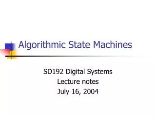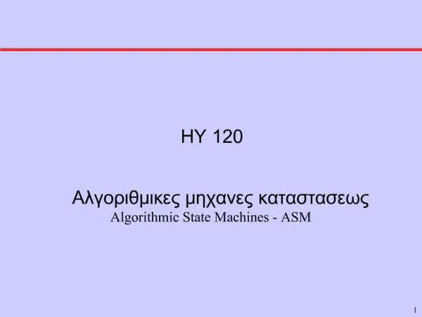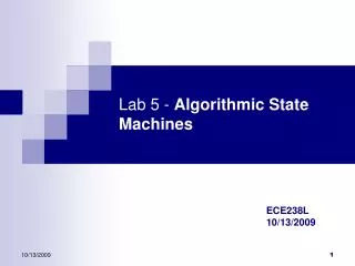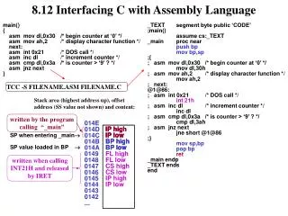
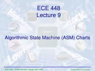
Algorithmic State Machine (ASM) Charts
ECE 448 Lecture 9. Algorithmic State Machine (ASM) Charts. Required reading. P. Chu, FPGA Prototyping by VHDL Examples Chapter 5, FSM. S. Brown and Z. Vranesic , Fundamentals of Digital Logic with VHDL Design Chapter 8.10, Algorithmic State Machine (ASM) Charts.

Algorithmic State Machine (ASM) Charts
E N D
Presentation Transcript
ECE 448 Lecture 9 Algorithmic State Machine (ASM) Charts ECE 448 – FPGA and ASIC Design with VHDL
Required reading • P. Chu, FPGA Prototyping by VHDL Examples • Chapter 5, FSM • S. Brown and Z. Vranesic, Fundamentals of Digital Logic with VHDL Design • Chapter 8.10, Algorithmic State Machine • (ASM) Charts ECE 448 – FPGA and ASIC Design with VHDL
Algorithmic State Machine (ASM) Charts ECE 448 – FPGA and ASIC Design with VHDL
Algorithmic State Machine Algorithmic State Machine – representation of a Finite State Machine suitable for FSMs with a larger number of inputs and outputs compared to FSMs expressed using state diagrams and state tables. ECE 448 – FPGA and ASIC Design with VHDL
Elements used in ASM charts (1) State name Output signals 0 (False) 1 (True) Condition or actions expression (Moore type) (a) State box (b) Decision box Conditional outputs or actions (Mealy type) (c) Conditional output box ECE 448 – FPGA and ASIC Design with VHDL
State Box • State box – represents a state. • Equivalent to a node in a state diagram or a row in a state table. • Contains register transfer actions or output signals • Moore-type outputs are listed inside of the box. • It is customary to write only the name of the signal that has to be asserted in the given state, e.g., z instead of z<=1. • Also, it might be useful to write an action to be taken, e.g., count <= count + 1, and only later translate it to asserting a control signal that causes a given action to take place (e.g., enable signal of a counter). State name Output signals or actions (Moore type) ECE 448 – FPGA and ASIC Design with VHDL
Decision Box • Decision box – indicates that a given condition is to be tested and the exit path is to be chosen accordingly The condition expression may include one or more inputs to the FSM. 0 (False) 1 (True) Condition expression ECE 448 – FPGA and ASIC Design with VHDL
Conditional Output Box • Conditional output box • Denotes output signals that are of the Mealy type. • The condition that determines whether such outputs are generated is specified in the decision box. Conditional outputs or actions (Mealy type) ECE 448 – FPGA and ASIC Design with VHDL
ASMs representing simple FSMs • Algorithmic state machines can model both Mealy and Moore Finite State Machines • They can also model machines that are of the mixed type ECE 448 – FPGA and ASIC Design with VHDL
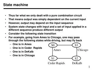
Reset w = 1 ¤ ¤ A z = 0 B z = 0 w = 0 w = 0 w = 1 w = 0 ¤ C z = 1 w = 1 Moore FSM – Example 2: State diagram ECE 448 – FPGA and ASIC Design with VHDL
Next state Present Output z state w = 0 w = 1 A A B 0 B A C 0 C A C 1 Moore FSM – Example 2: State table ECE 448 – FPGA and ASIC Design with VHDL
ASM Chart for Moore FSM – Example 2 ECE 448 – FPGA and ASIC Design with VHDL
Example 2: VHDL code (1) USE ieee.std_logic_1164.all ; ENTITY simple IS PORT ( clock : IN STD_LOGIC ; resetn : IN STD_LOGIC ; w : IN STD_LOGIC ; z : OUT STD_LOGIC ) ; END simple ; ARCHITECTURE Behavior OF simple IS TYPE State_type IS (A, B, C) ; SIGNAL y : State_type ; BEGIN PROCESS ( resetn, clock ) BEGIN IF resetn = '0' THEN y <= A ; ELSIF (Clock'EVENT AND Clock = '1') THEN ECE 448 – FPGA and ASIC Design with VHDL
Example 2: VHDL code (2) CASE y IS WHEN A => IF w = '0' THEN y <= A ; ELSE y <= B ; END IF ; WHEN B => IF w = '0' THEN y <= A ; ELSE y <= C ; END IF ; WHEN C => IF w = '0' THEN y <= A ; ELSE y <= C ; END IF ; END CASE ; ECE 448 – FPGA and ASIC Design with VHDL
Example 2: VHDL code (3) END IF ; END PROCESS ; z <= '1' WHEN y = C ELSE '0' ; END Behavior ; ECE 448 – FPGA and ASIC Design with VHDL
Reset ¤ w = 1 z = 0 ¤ ¤ w = 0 z = 0 w = 1 z = 1 A B ¤ w = 0 z = 0 Mealy FSM – Example 3: State diagram ECE 448 – FPGA and ASIC Design with VHDL
ASM Chart for Mealy FSM – Example 3 ECE 448 – FPGA and ASIC Design with VHDL
Example 3: VHDL code (1) LIBRARY ieee ; USE ieee.std_logic_1164.all ; ENTITY Mealy IS PORT ( clock : IN STD_LOGIC ; resetn : IN STD_LOGIC ; w : IN STD_LOGIC ; z : OUT STD_LOGIC ) ; END Mealy ; ARCHITECTURE Behavior OF Mealy IS TYPE State_type IS (A, B) ; SIGNAL y : State_type ; BEGIN PROCESS ( resetn, clock ) BEGIN IF resetn = '0' THEN y <= A ; ELSIF (clock'EVENT AND clock = '1') THEN ECE 448 – FPGA and ASIC Design with VHDL
Example 3: VHDL code (2) CASE y IS WHEN A => IF w = '0' THEN y <= A ; ELSE y <= B ; END IF ; WHEN B => IF w = '0' THEN y <= A ; ELSE y <= B ; END IF ; END CASE ; ECE 448 – FPGA and ASIC Design with VHDL
Example 3: VHDL code (3) END IF ; END PROCESS ; z <= '1' WHEN (y = B) AND (w=‘1’) ELSE '0' ; END Behavior ; ECE 448 – FPGA and ASIC Design with VHDL
Control Unit Example: Arbiter (1) reset g1 r1 Arbiter g2 r2 g3 r3 clock ECE 448 – FPGA and ASIC Design with VHDL
Control Unit Example: Arbiter (2) 000 Reset Idle 0xx 1xx ¤ gnt1 g = 1 1 1xx x0x 01x ¤ gnt2 g = 1 2 x1x xx0 001 ¤ gnt3 g = 1 3 xx1 ECE 448 – FPGA and ASIC Design with VHDL
Control Unit Example: Arbiter (3) ECE 448 – FPGA and ASIC Design with VHDL
ASM Chart for Control Unit - Example 4 ECE 448 – FPGA and ASIC Design with VHDL
Example 4: VHDL code (1) LIBRARY ieee; USE ieee.std_logic_1164.all; ENTITY arbiter IS PORT ( Clock, Resetn : IN STD_LOGIC ; r : IN STD_LOGIC_VECTOR(1 TO 3) ; g : OUT STD_LOGIC_VECTOR(1 TO 3) ) ; END arbiter ; ARCHITECTURE Behavior OF arbiter IS TYPE State_type IS (Idle, gnt1, gnt2, gnt3) ; SIGNAL y : State_type ; ECE 448 – FPGA and ASIC Design with VHDL
Example 4: VHDL code (2) BEGIN PROCESS ( Resetn, Clock ) BEGIN IF Resetn = '0' THEN y <= Idle ; ELSIF (Clock'EVENT AND Clock = '1') THEN CASE y IS WHEN Idle => IF r(1) = '1' THEN y <= gnt1 ; ELSIF r(2) = '1' THEN y <= gnt2 ; ELSIF r(3) = '1' THEN y <= gnt3 ; ELSE y <= Idle ; END IF ; WHEN gnt1 => IF r(1) = '1' THEN y <= gnt1 ; ELSE y <= Idle ; END IF ; WHEN gnt2 => IF r(2) = '1' THEN y <= gnt2 ; ELSE y <= Idle ; END IF ; ECE 448 – FPGA and ASIC Design with VHDL
Example 4: VHDL code (3) WHEN gnt3 => IF r(3) = '1' THEN y <= gnt3 ; ELSE y <= Idle ; END IF ; END CASE ; END IF ; END PROCESS ; g(1) <= '1' WHEN y = gnt1 ELSE '0' ; g(2) <= '1' WHEN y = gnt2 ELSE '0' ; g(3) <= '1' WHEN y = gnt3 ELSE '0' ; END Behavior ; ECE 448 – FPGA and ASIC Design with VHDL
Incorrect ASM charts: Chapter 10