State Machine
Finite State Machines (FSMs) are crucial in digital design, blending combinational logic with storage to remember states and transition based on inputs. This guide covers the fundamentals of FSMs, illustrating key concepts such as state diagrams and state transition functions. Discover how FSMs form intuitive descriptions for systems with discrete dynamics, and explore practical examples like combination locks and odd parity checkers. Learn the steps to convert state transition tables into actual digital circuits, enhancing your design capabilities.

State Machine
E N D
Presentation Transcript
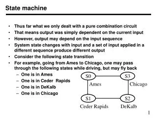
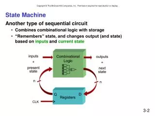
State Machine • Another type of sequential circuit • Combines combinational logic with storage • “Remembers” state, and changes output (and state) based on inputs and current state
4 1 8 4 30 25 5 20 10 15 Combinational vs. Sequential • Two types of “combination” locks Combinational Success depends only onthe values, not the order in which they are set. Sequential Success depends onthe sequence of values (e.g, R-13, L-22, R-3).
State • The state of a system is a snapshot ofall the relevant elements of the systemat the moment the snapshot is taken. • Examples: • The state of a basketball game can be represented bythe scoreboard. • Number of points, time remaining, possession, etc. • The state of a tic-tac-toe game can be represented bythe placement of X’s and O’s on the board.
State of Sequential Lock • Our lock example has four different states,labelled A-D:A: The lock is not open, and no relevant operations have been performed. • B: The lock is not open, and the user has completed the R-13 operation. • C: The lock is not open, and the user has completed R-13, followed by L-22. • D: The lock is open. • (user has completed R-13, L-22 and then R-3)
State Diagram • Shows states and actions that cause a transition between states.
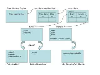
Definition of a Finite State Machine • A set of input events • A set of output events • A set of states • A function that maps states and input to output • A function that maps states and inputs to states (which is called a state transition function) • Must be complete • A description of the initial state • A finite state machine is one that has a limited or finite number of possible states.
Example 2: A Door Combination Lock entry code is the 4-bit sequence “0110” Partial Complete
Why Finite State Machines (FSMs) • A FSM is simple and intuitive way of describing a system which has discrete dynamics (State Transition Diagrams). • An FSM is an “abstract machine.” That means that we use a mathematical description of the machine to reason about it without actually building it. • A FSM can be directly and unambiguously converted into a digital electronic circuits.
Step 2: Code STT in numbers (NS) (NS)
Step 3a: Next State Logic for 1 D-Latch Output Inputs NS= (~PS S) + (PS ~S)
Step 3b: Output Logic Output Inputs R= PS
The Clock • Frequently, a clock circuit triggers transition fromone state to the next. • At the beginning of each clock cycle,state machine makes a transition,based on the current state and the external inputs. • Not always required. In lock example, the input itself triggers a transition. “1” “0” One Cycle time
Master-Slave Flipflop • A pair of gated D-latches, to isolate next state from current state. PS NS PS During 1st phase (clock=1),previously-computed statebecomes current state and issent to the logic circuit. During 2nd phase (clock=0),next state, computed bylogic circuit, is stored inLatch A.