Download
1 / 47
470 likes | 582 Vues
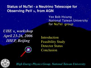
Searching for ultra high energy cosmic neutrinos behind a mountain. Min-Zu Wang 王名儒 for the NuTel Collaboration. U.C. Davis - NTU December 15, 2008. Introduction Feasibility Study Detector Status Conclusion. High Energy Physics Group, National Taiwan University.

E N D
Searching for ultra high energy cosmic neutrinos behind a mountain Min-Zu Wang 王名儒 for the NuTel Collaboration U.C. Davis - NTU December 15, 2008 Introduction Feasibility Study Detector Status Conclusion High Energy Physics Group, National Taiwan University
UHECR Detector Conventional Detector ? Window of Opportunity
Earth Skimming Earth Skimming + Mountain Penetrating Cherenkov vs. fluorescence Cross Section ~ E1.4 Telescope t appearanceexperiment! Sensitive to nt ne: electron energy mostly absorbed in mountain nm: no extensive air shower
1 2 3 Three simulation stages 1. Mountain simulation: +N cross-section • inelasticity • energy loss of tau 2. Air shower simulation: Cerenkov photons • decay mode • CORSIKA detailed air shower simulation vs. fast simulation 3. Detector performance simulation • light propagation + Q.E. • pixelization for triggers • reconstruction
inside mountain • SM CC +N cross-section • Inelasticity & energy loss are calculated by G.L. Lin, J.J. Tseng, T.W. Yeh, F.F. Lee of NCTU • Range (distance when survival prob = e-1) are calculated by M.A. Huang
Tau flux No dE/dx dE/dx • Tau flux: • Fast simulation: single interaction inside target • Full-scale transport eq.: Consider multiple interactions ... • Conversion efficiency: • optimal thickness ~ several times of • Energy loss decrease conversion efficiency
Lateral profile of Cerenkov photons for horizontal shower (CORSIKA ) 1018 eV 1016 eV 1014 eV • Similar profile for showers produced by e– and • Cerenkov ring distance ~ (L-Rmax)Tan c • Outside ring, photon density ~ exponential decay • Detector can trigger far away from Cerenkov ring
Photons numbers vs opening angle Photon density • 1 PeV shower • Shower core to detector plan 30 km away • Serious drop with attenuation No atten. Atten.=15km Opening angle (radian)
The Signal and Background Pattern Cherenkov: ns pulse, angular span ~ 1.5 degrees Night Sky Background (mean) Measured at Lulin observatory: 2.0 x10³ ph/ns/m2/sr A magnitude 0 star gives 7.6 ph/m2/ns in (290,390) nm Cosmic Ray background very small Cluster-based trigger algorithm Random Background with NSB flux 1 km away from a 1 PeV e- shower
H H L H n1 n2 n3 n8 H n4 n7 n6 n5 Trigger Configuration • Single Pixel Trigger: One pixel pass energy threshold H • Duo Trigger: Two neighbouring pixels pass threshold H • H-L Trigger: Two neighbouring pixels with one passes high threshold H and the other one passes low threshold L • Sum Trigger: 1. (3x3) trigger cell 2. Central pixel pass high threshold H Neighbour Npe Sum pass threshold A=n1+n2+…+n8 Night Sky Background: H • Npe Follows Poisson distribution: Prob(n;μ) = e-μμn/n!, μ = <Npe> Φ tg A FOV εAεq , Φ= 200/ns/m2/sr A=1m2 FOV=0.5ox0.5oεA =0.5 εq =0.2 μ =0.039 tg=25ns ; m=0.076 tg=50ns Range<0.5km: Majority of photon arrives within 25 ns Most of photons arrives within 50 ns
Trigger Efficiency for Electron Shower Sum Trigger gives The largest range 1.1km for etrig=90% Sum trigger are similar Other Three triggers are similar Conservative estimation is 200 γneeded 90%
E, x, y, , N1, T1, x1 , y1,1, 1 N2, T2, x2 , y2,2, 2 2 1 Preliminary Reconstruction • Reconstruction: Minimize 2 for x,y,,, and E • Two Detectors Separated by ~ 100m
Possibility for Reconstruction • Possible to Reconstruct Events • Angular Error within 1° • Energy Error ~ 40% • Reconstruction Efficiency > 90% if triggered
Sensitivity • Defined as reachable upper limit of flux • Assume F(En) = F0 En-2 • Assume no signal in 2 years of observation • Feldman-Cousin method for upper limits: 2.44 signal events • Theo1: ~ 0.5 events/year 4.7 ×10²
Electronics Device of NuTel (schematic) distribution board 32events size light collector send a Interrupt every 16 events light collector
Signal-sharing plate 32 – channels Data Collection Module in cPCI Hamamatsu 8x8 MPMT 16-channels preamplifier 10 bit x 40 MHz ADC cycle RAM buffer RAM 2 m cable HV power supply Preamp. FADC Trigger daisy chain PMT Trigger Front-end electronics Inside cPCI (PXI) chassis DAQ Multi-anode PMT (MAPMT) “H7546” of 8x8 pixels is used as photon-sensitive device Schematics of electronics
Signal-sharing plate 32 – channels Data Collection Module in cPCI Hamamatsu 8x8 MPMT 16-channels preamplifier 10 bit x 40 MHz ADC cycle RAM buffer RAM 2 m cable HV power supply Preamp. FADC Trigger daisy chain PMT Trigger Front-end electronics Inside cPCI (PXI) chassis DAQ Computer-controlled HV power supply “VHQ-202M” in VME is used for MAPMT, 2 channels/module, 1 channel supplies 4 MAPMT (256 pixels) “SBS” PCIVME adapter Schematics of electronics
Signal-sharing plate 32 – channels Data Collection Module in cPCI Hamamatsu 8x8 MPMT 16-channels preamplifier 10 bit x 40 MHz ADC cycle RAM buffer RAM 2 m cable HV power supply Preamp. FADC Trigger daisy chain PMT Trigger Front-end electronics Inside cPCI (PXI) chassis DAQ “SBS” PCIVME adapter Signal-sharing plate is used for increasing dynamic range of the system in factor of about 10-20 times Schematics of electronics
Signal-sharing plate 32 – channels Data Collection Module in cPCI Hamamatsu 8x8 MPMT 16-channels preamplifier 10 bit x 40 MHz ADC cycle RAM buffer RAM 2 m cable HV power supply Preamp. FADC Trigger daisy chain PMT Trigger Front-end electronics Inside cPCI (PXI) chassis DAQ 16-channels charge sensitive preamplifier transforms charge into voltage for digitising by pipelined ADC Schematics of electronics
Signal-sharing plate 32 – channels Data Collection Module in cPCI Hamamatsu 8x8 MPMT 16-channels preamplifier 10 bit x 40 MHz ADC cycle RAM buffer RAM 2 m cable HV power supply Preamp. FADC Trigger daisy chain PMT Trigger Front-end electronics Inside cPCI (PXI) chassis DAQ Holes for mechanical purposes in future 4 preamplifier boards and signal- sharing plate are connected to one MAPMT Schematics of electronics
Signal-sharing plate 32 – channels Data Collection Module in cPCI Hamamatsu 8x8 MPMT 16-channels preamplifier 10 bit x 40 MHz ADC cycle RAM buffer RAM 2 m cable HV power supply Preamp. FADC Trigger daisy chain PMT Trigger Front-end electronics Inside cPCI (PXI) chassis DAQ 32-channels Data Collection module in cPCI (PXI) processes signals from 32 channels, has Trigger logic on the module and memory of 256 ADC clocks. If one event is 8 clocks (200 ns), memory could keep up to 32 events. Schematics of electronics
Signal-sharing plate 32 – channels Data Collection Module in cPCI Hamamatsu 8x8 MPMT 16-channels preamplifier 10 bit x 40 MHz ADC buffer RAM cycle RAM 2 m cable HV power supply Preamp. FADC Trigger daisy chain PMT Trigger Front-end electronics Inside cPCI (PXI) chassis DAQ System (CPU) card There will be 16 DCM boards (512 channels) inside one PXI chassis DCM Active cPCI extender for debugging Schematics of electronics
Signal-sharing plate 32 – channels Data Collection Module in cPCI Hamamatsu 8x8 MPMT 16-channels preamplifier 10 bit x 40 MHz ADC cycle RAM buffer RAM 2 m cable HV power supply Preamp. FADC Trigger daisy chain PMT Trigger Front-end electronics Inside cPCI (PXI) chassis DAQ DAQ – in Linux, inside cPCI (PXI) CPU card Schematics of electronics
Pre-amp. linearity • Use attenuation to send decreasing pulses in height. • Intercept with y axis is 1.025mV. X10
Calibration method • Every step taking 96 events. Taking the peak value clock value (usually 5th clock). Calculating every step’s mean and rms values. • Error = rms/ square(N) • Using first order fn. (line) to fit. • intercept with y-axis is pedestal. Fit result Fit pedestal DAC value
ResultDCM#22 potentiometer affect pedestal • Pedestal distribution
Single Pulse into Pre-amp • Output with paw fit, divide by 3 regions. (a) Pre-amp.#37 ch.2 • (b) fitting function tau1 tau2 (b)
tau1 and tau2 over 512 channels -20% +20% -5% +5% mean value of tau2=185.9ns mean value of tau1=12.26ns
35ns delay • The waveform can still be fit well. • Dash-line is only one pulse response. • Its height is lower than single peak.
Results • Event lost rate = total lost event / (50000+total lost event)
Demands of Optical system • Smaller image size is better. • Smaller spot size is better. • Wavelength: UV region, because it has more Cerenkov light as 1/l2. Photo sensor: 8X8 MAPMTs with 512 pixels Aperture~1m2 FOV: 16o horizontally 8o vertically
Schmidt Mirror System D:1.6m, finally we made 1.8m Aspherical Corrector Lens mainly eliminate spherical aberration. D:1.14m Curved image surface
Transmittance of curved Light collector & total T 1. Loss of dead zone is considered. 2. The minimal loss is about 34% between 30~35mm. Total Transmittance ~ 0.94 (shadowing effect) x 0.93 (T of lens) x 0.93 (R of mirror) x 0.66 (light collector) x 0.94 (gap between pitch of MAMPT) = 50.5.%
Measurement of the Aspherical Lens at KEK An image of a blue laser through the lens is measured on the screen. Compare the measurement result and the prediction. D:2m Result
Foucault test at KEK RESULT: 1801±2mm Design value: 1800mm
NuTel at NTU Gravity center, make rotation easier. Trick of alignment of position & tilt: make incident and reflected light overlapped.
Spot size measurement Origin of optical system. . y z x
RMS diameter:1.847 Spot size for 0O 1 2 y 1 x 4 3 2 RMS diameter: 1.338 RMS diameter:1.382 4 3
RMS diameter: 0.847 RMS diameter: 1.323 Θy=0O,Θx=10O y 11 9 10 9 x 12 11 RMS diameter: 0.953 RMS diameter:1.462 Θy=0O ,Θx=-10O 12 10
Spot size measurement- • Auto-scan setup done • Computer controlled 4 d linear-guide (x, z axes , and two rotation axes) combined with digital camera + Laser pen
Mei-Fong (2100m) • Site survey in summer 2008 • Lu-Lin Zan Chung (2700m) • Kuan-young (3092m)
Conclusion • NuTel is an experiment dedicated to earth skimming for t appearance • The PeV cosmic nt rate is ~ 0.5 event/year • Cost is low: O(1) million US dollars to build it • First set of telescope is almost ready • UHECR observation in Taiwan: prototype deployment in 2009