FLUOROSCOPY
FLUOROSCOPY. Since Thomas A. Edison invented the fluoroscope in 1896, it has served as a valuable tool in the practice of radiology. .


FLUOROSCOPY
E N D
Presentation Transcript
Since Thomas A. Edison invented the fluoroscope in 1896, it has served as a valuable tool in the practice of radiology.
A radiologic technique in which a fluoroscope is used to visually examine the body or an organ. (A fluoroscope utilizes an X-ray tube and fluorescent screen, with the area to be viewed placed between the screen and the tube.) This immediate imaging, when coupled with an image intensifier, is invaluable in situations such as cardiac catheterization, thin needle biopsies of tumors, and localization of foreign bodies.
The kVp of operation depends entirely on the section of the body that is being examined. Fluoroscopic equipment allows the radiologist to select an image brightness level that is subsequently maintained automatically by varying the kVp, the mA, or sometimes both. This feature of the fluoroscope is called automatic brightness control (ABC).
mA VARIES WITH THE BODY PART • USUALLY 1-5 mA
The principal advantage of image-intensified fluoroscopy over earlier types of fluoroscopy is increased image brightness. Just as it is much more difficult to read a book in dim illumination than in bright illumination, it is much harder to interpret a dim fluoroscopic image than a bright one.
Human Vision The structures in the eye that are responsible for the sensation of vision are called rods and cones. Light incident on the eye must first pass through the cornea, a transparent protective covering, and then through the lens, where the light is focused onto the retina
When light arrives at the retina, it is detected by the rods and the cones. Rods and cones are small structures; more than 100,000 of them are found per square millimeter of retina. The cones are concentrated at the center of the retina in an area called the fovea centralis. Rods, on the other hand, are most numerous on the periphery of the retina. No rods are found at the fovea centralis.
The rods are sensitive to low light levels and are stimulated during dim light situations. The threshold for rod vision is approximately 2 lux. Cones, on the other hand, are less sensitive to light; their threshold is only approximately 100 lux, but cones are capable of responding to intense light levels, whereas rods cannot.
Cones are used primarily for daylight vision, called photopic vision, and rods are used for night vision, called scotopic vision.
Cones perceive small objects much better than rods do. This ability to perceive fine detail is called visual acuity. Cones are also much better at detecting differences in brightness levels. This property of vision is called contrast perception. Furthermore, cones are sensitive to a wide range of wavelengths of light. Cones perceive color, but rods are essentially color-blind. Under scotopic conditions, the sensitivity of the eye is greatest in the green part of the spectrum at about 555 nm.
During fluoroscopy, maximum image detail is desired; this requires high levels of image brightness. The image intensifier was developed principally to replace the conventional fluorescent screen, which had to be viewed in a darkened room and then only after 15 minutes of dark adaptation The image intensifier raises illumination into the cone vision region, where visual acuity is greatest.
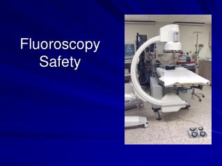
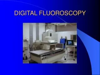
IMAGE INTENSIFIER • The image-intensifier tube is a complex electronic device that receives the image-forming x-ray beam and converts it into a visible-light image of high intensity. The tube components are contained within a glass or metal envelope that provides structural support but more importantly maintains a vacuum. When installed, the tube is mounted inside a metal container to protect it from rough handling and breakage.
X-rays that exit the patient and are incident on the image-intensifier tube are transmitted through the glass envelope and interact with the input phosphor, which is cesium iodide (CsI). When an x-ray interacts with the input phosphor, its energy is converted into visible light; this is similar to the effect of radiographic intensifying screens. The CsI crystals are grown as tiny needles and are tightly packed in a layer of approximately 300 μm Each crystal is approximately 5 μm in diameter. This results in microlight pipes with little dispersion and improved spatial resolution.
The next active element of the image-intensifier tube is the photocathode, which is bonded directly to the input phosphor with a thin, transparent adhesive layer. The photocathode is a thin metal layer usually composed of cesium and antimony compounds that respond to stimulation of input phosphor light by the emission of electrons. The photocathode emits electrons when illuminated by the input phosphor. This process is known as photoemission. The term is similar to thermionic emission, which refers to electron emission that follows heat stimulation. Photoemission is electron emission that follows light stimulation.
The image-intensifier tube is approximately 50 cm long. A potential difference of about 25,000 V is maintained across the tube between photocathode and anode so that electrons produced by photoemission will be accelerated to the anode
The anode is a circular plate with a hole in the middle through which electrons pass to the output phosphor, which is just the other side of the anode and is usually made of zinc cadmium sulfide. The output phosphor is the site where electrons interact and produce light.
For the image pattern to be accurate, the electron path from the photocathode to the output phosphor must be precise. The engineering aspects of maintaining proper electron travel are called electron optics because the pattern of electrons emitted from the large cathode end of the image-intensifier tube must be reduced to the small output phosphor. The devices responsible for this control, called electrostatic focusing lenses, are located along the length of the image-intensifier tube. The electrons arrive at the output phosphor with high kinetic energy and contain the image of the input phosphor in minified form.
The increased illumination of the image is due to the multiplication of light photons at the output phosphor compared with x-rays at the input phosphor and the image minification from input phosphor to output phosphor. The ability of the image intensifier to increase the illumination level of the image is called its brightness gain. The brightness gain is simply the product of the minification gain and the flux gain.
BRIGTNESS GAIN (B.G.) B.G. = Minification gain x Flux gain MOST INTENSIFIERS: 5,000 – 20,000
The interaction of these high-energy electrons with the output phosphor produces a considerable amount of light. Each photoelectron that arrives at the output phosphor produces 50 to 75 times as many light photons as were necessary to create it. This ratio of the number of light photons at the output phosphor to the number of x-rays at the input phosphor is the flux gain.
FLUX GAIN # OF PHOTONS AT THE OUTPUT PHOSPHOR # OF PHOTONS AT THE INPUT PHOSPHOR
The minification gain is the ratio of the square of the diameter of the input phosphor to the square of the diameter of the output phosphor. Output phosphor size is fairly standard at 2.5 or 5 cm. Input phosphor size varies from 10 to 35 cm and is used to identify image-intensifier tubes.
MINIFICATION GAIN SQUARE OF THE INPUT PHOSPHOR DIAMETER SQUARE OF THE OUTPUT PHOSPHOR DIAMETER
Brightness gain is now defined as the ratio of the illumination intensity at the output phosphor, measured in candela per meter squared (cd/m2) to the radiation intensity incident on the input phosphor, measured in milliroentgens per second (mR/s). This quantity is called the conversion factor and is approximately 0.01 times the brightness gain. The conversion factor is the proper quantity for expressing image intensification.
Image intensifiers have conversion factors of 50 to 300. These correspond to brightness gains of 5000 to 30,000.
Internal scatter radiation in the form of x-rays, electrons, and particularly light can reduce the contrast of image-intensifier tubes through a process called veiling glare. Advanced II tubes have output phosphor designs that reduce veiling glare.
Multifield Image Intensification Most image intensifiers are of the multifield type. Multifield image intensifiers provide considerably greater flexibility in all fluoroscopic examinations and are standard components in digital fluoroscopy. Trifield tubes come in various sizes, but perhaps the most popular is 25/17/12 cm.
When a switch is made to the 17-cm mode, the voltage on the electrostatic focusing lenses increases; this causes the electron focal point to move farther from the output phosphor. Consequently, only electrons from the center 17-cm diameter of the input phosphor are incident on the output phosphor. The principal result of this change in focal point is to reduce the field of view. The image now appears magnified because it still fills the entire screen on the monitor. Use of the smaller dimension of a multifield image-intensifier tube always results in a magnified image, with a magnification factor in direct proportion to the ratio of the diameters. A 25/17/12 tube operated in the 12-cm mode produces an image that is times larger than the image produced in the 25-cm mode.
The portion of any image that results from the periphery of the input phosphor is inherently unfocused and suffers from vignetting, that is, a reduction in brightness at the periphery of the image.
MAGNIFICATION MODE RESULTS IN: • Better spatial resolution • Better contrast resolution • Higher patient dose
FLUOROSCOPIC DATA AQUSITION-IMAGE INTENSIFIED SYSTEM • X-RAY TUBE • PATIENT • IMAGE INTENSIFIER • OUTPUT PHOSPHOR • CAMERA • MONITOR
Two methods are used to electronically convert the visible image on the output phosphor of the image intensifier into an electronic signal: • Thermionic television camera tube • The solid state charge-coupled device (CCD).
The television camera consists of cylindrical housing, approximately 15 mm in diameter by 25 cm in length, that contains the heart of the television camera tube. It also contains electromagnetic coils that are used to properly steer the electron beam inside the tube. A number of such television camera tubes are available for television fluoroscopy, but the vidicon and its modified version, the Plumbicon, are used most often.
Image intensifiers and television camera tubes are manufactured so that the output phosphor of the image-intensifier tube is the same diameter as the window of the television camera tube, usually 2.5 or 5 cm. Two methods are commonly used to couple the television camera tube to the image-intensifier tube